Automatic Transfer Switches (ATS) & Static Transfer Switches (STS) for Data Centers
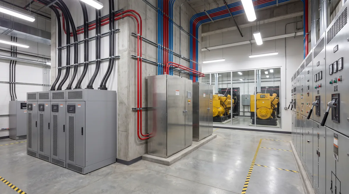
Between the moment a utility feed fails and the moment your servers notice, a transfer switch makes an invisible decision that determines whether your data center stays online or goes dark. Transfer switches are the critical junction point in every data center power path, sitting between utility and generator, between redundant UPS modules, and between independent power distribution chains. Yet they are among the least understood components in the power infrastructure stack.
This guide examines the two primary transfer switch technologies used in data centers: Automatic Transfer Switches (ATS) that use mechanical contactors and Static Transfer Switches (STS) that use solid-state electronics. We cover where each belongs in the power chain, how they interact with UPS systems, power distribution units, and switchgear, and the sizing considerations for modern high-density GPU workloads.
How Transfer Switches Work in Data Centers
A transfer switch monitors two independent power sources and transfers the connected load from the preferred source to the alternate source when it detects a failure condition. The fundamental difference between ATS and STS is the transfer mechanism and, consequently, the speed at which the switch executes the transfer.
Automatic Transfer Switches (ATS): Mechanical Transfer
An ATS uses electromechanical contactors (large relays or motor-driven switch mechanisms) to physically connect the load to one of two power sources. When the preferred source fails or drifts outside acceptable voltage and frequency parameters, the ATS controller signals the contactor mechanism to open the connection to the failing source and close the connection to the alternate source.
This mechanical process involves physical movement of contact assemblies, which takes time. Typical ATS transfer times range from 100 to 500 milliseconds (6 to 30 electrical cycles at 60 Hz). Some fast-operating ATS designs can achieve 60-100 millisecond transfers, but they still require measurable time for the contactor mechanism to actuate.
ATS operation follows one of two transfer modes:
- Open transition (break-before-make): The ATS disconnects from the failing source before connecting to the alternate source. This creates a momentary interruption (the transfer time) during which the load has no external power. This is the standard mode for utility-to-generator transfers, where the UPS battery absorbs the interruption.
- Closed transition (make-before-break): The ATS briefly connects both sources in parallel (for less than 100 milliseconds) before disconnecting the failing source. This eliminates any interruption but requires both sources to be synchronized in voltage, frequency, and phase angle. Not all utility-generator combinations support closed transition.
Static Transfer Switches (STS): Electronic Transfer
An STS uses silicon-controlled rectifiers (SCRs, also called thyristors) to electronically switch between two power sources. Since SCRs have no moving parts and can turn on within a fraction of an electrical cycle, STS transfer times are dramatically faster than ATS: typically 4 to 8 milliseconds (less than half a cycle at 50/60 Hz).
The STS controller continuously monitors both sources and evaluates voltage, frequency, phase angle, and rate of change. When the preferred source degrades, the controller fires the alternate-source SCRs before the preferred-source SCRs fully commutate off. Advanced STS models use predictive algorithms that detect source degradation trends and begin the transfer process proactively, achieving sub-4-millisecond transfers.
STS transfers are inherently closed transition: the alternate source connects before the preferred source fully disconnects, with the overlap measured in microseconds. This provides effectively zero-break transfer for the downstream load. However, the STS can also perform open transition if the two sources are not synchronized (different frequency or phase angle), at the cost of a slightly longer transfer time.
Where ATS and STS Belong in the Data Center Power Chain
ATS: Upstream at the Utility-Generator Interface
The primary application for ATS in data centers is at the point where utility power enters the facility and where standby generators connect to the distribution system. When the utility fails, the ATS:
- Detects the utility voltage drop or loss (typically 5-10 seconds of monitoring to distinguish a true outage from a momentary disturbance)
- Sends a start signal to the standby generator
- Waits for the generator to reach rated voltage and frequency (10-15 seconds for a typical standby diesel generator)
- Transfers the load from utility to generator (100-500 milliseconds for the actual transfer)
The total time from utility failure to generator-powered operation is typically 15 to 30 seconds. During this entire period, the UPS system operates on battery, providing uninterrupted power to the IT load. The ATS transfer time is irrelevant to the IT equipment because the UPS isolates it completely.
This is why mechanical ATS units are perfectly adequate at the utility-generator interface: the UPS provides a complete power bridge, and the ATS does not need sub-cycle transfer speed. What matters at this level is the ATS's reliability over decades of standby operation, its ability to handle high fault currents, and its compatibility with the generator's voltage regulation characteristics.
STS: Downstream for Critical Load Switching
Static transfer switches operate downstream in the power chain, typically at the PDU (Power Distribution Unit) or row level, where they provide sub-cycle switching between two independent power feeds. The most common STS applications in data centers include:
- Dual-bus to single-bus conversion: In 2N redundant power architectures, each power bus operates independently. An STS can feed a critical single-corded load from either bus, automatically transferring if one bus fails. This allows single-corded equipment to benefit from 2N utility and UPS redundancy without requiring dual power supplies in every device.
- UPS output redundancy: An STS between two independent UPS outputs provides automatic transfer if one UPS module fails, undergoes maintenance, or produces out-of-specification output. This is particularly important during UPS maintenance events when one module is bypassed for service.
- Concurrent maintainability: STS units enable concurrent maintenance of upstream power components without interrupting the IT load. When one power path is taken offline for switchgear maintenance, transformer testing, or UPS module replacement, the STS seamlessly transfers the load to the alternate path.
The speed of STS transfer is critical because downstream equipment may not have battery-backed power supplies. Single-corded servers, network switches, storage arrays, and especially high-power GPU servers rely on their internal power supplies' hold-up time (typically 10-20 milliseconds for modern ATX/EPS power supplies with PFC circuits) to ride through any power interruption. The STS must complete its transfer within this window.
Transfer Switch Architecture by Data Center Tier
The Uptime Institute's Tier Classification system defines escalating levels of redundancy, and transfer switch deployment varies accordingly:
| Tier | ATS Application | STS Application | Expected Availability |
|---|---|---|---|
| Tier I (Basic) | None (single utility path) | None | 99.671% |
| Tier II (Redundant Components) | Single ATS for utility-generator transfer | Optional | 99.741% |
| Tier III (Concurrently Maintainable) | Multiple ATS units for N+1 generator config | STS at PDU/row level for concurrent maintainability | 99.982% |
| Tier IV (Fault Tolerant) | Dual-path ATS with auto-transfer on any path failure | STS at every critical load point, 2N throughout | 99.995% |
Tier III facilities, which represent the minimum standard for enterprise and colocation data centers, typically deploy ATS units at the utility-generator interface and STS units at the PDU level to achieve concurrent maintainability. This allows any single power component to be taken offline for maintenance without interrupting the IT load.
Sizing Transfer Switches for AI and GPU Workloads
The explosive growth of GPU-accelerated AI workloads creates unique challenges for transfer switch sizing. Traditional server racks drew 5-15 kW, making 100A or 200A transfer switches standard. Modern GPU racks running NVIDIA H100, H200, or GB300 configurations draw 30-120+ kW per rack, fundamentally changing the transfer switch selection process.
Key Sizing Considerations
- Continuous current rating: The ATS or STS must carry the maximum expected continuous load with adequate margin. Industry practice is 125% of the maximum continuous load (per NEC Article 700.5). A 50 kW GPU rack at 208V three-phase draws approximately 139A continuous, requiring a 200A-rated transfer switch minimum.
- Inrush current withstand: GPU power supplies generate significant inrush current during power-on, and transfer switch closure creates a similar inrush condition. The ATS/STS closing rating (also called withstand rating) must exceed the worst-case inrush scenario, typically 150-200% of rated current for several cycles. Always verify the manufacturer's published inrush withstand specification.
- Fault current rating: Transfer switches must be rated for the available fault current at their point of installation. High-density GPU environments with large transformers and short conductors can have fault current levels of 65,000A or more. Both ATS and STS must carry a Short Circuit Current Rating (SCCR) equal to or exceeding the available fault current.
- Harmonic content: GPU server power supplies with active PFC circuits generate harmonic currents, particularly at the 3rd, 5th, and 7th harmonics. These harmonics increase RMS current above the fundamental frequency component, and transfer switches must be rated for the total RMS current including harmonics. In severe cases, the true RMS current can be 10-15% higher than the fundamental component.
High-Density Deployment Patterns
For high-density deployments exceeding 30 kW per rack, transfer switch architecture often shifts from per-rack units to per-row or per-zone configurations. A row of eight GPU racks drawing 50 kW each requires 400 kW of transfer capacity. Deploying individual 200A ATS/STS units per rack adds cost, complexity, and failure points. Instead, a single 1200A or 1600A STS feeding the entire row through a power panel or switchboard reduces equipment count while maintaining transfer speed.
This row-level or zone-level approach also simplifies power budgeting because the diversity factor across multiple GPU racks reduces the peak concurrent demand below the sum of individual rack peaks. A row of eight racks rated at 50 kW each (400 kW total) may have a diversity factor of 0.85-0.90, reducing the actual peak to 340-360 kW and allowing slightly smaller transfer equipment.
Bypass Isolation and Maintenance Access
Both ATS and STS units require periodic maintenance, testing, and eventual replacement. Bypass isolation capability determines whether the transfer switch can be maintained without interrupting the connected load.
ATS Bypass Isolation
ATS units for data center applications should include an integral bypass-isolation switch. This manually operated switch allows an operator to connect the load directly to one power source, bypassing the ATS entirely, and then electrically isolate the ATS contacts for safe maintenance. The bypass-isolation sequence is:
- Transfer load to the desired source (if not already on it)
- Engage the bypass switch to connect load directly to source
- Isolate the ATS contacts from both sources
- Perform maintenance on the ATS mechanism
- Reverse the sequence to restore automatic operation
During bypass, the load is connected to a single source with no automatic transfer protection. If that source fails, a manual intervention is required. This is acceptable for planned maintenance windows but represents a temporary reduction in power redundancy.
STS Bypass and Wraparound Configurations
STS units similarly offer bypass-isolation capability, but the bypass is especially important because SCR components degrade over time and may require replacement. STS bypass allows the load to be connected directly to the preferred source while the SCR assemblies are serviced.
For maximum availability, some data centers deploy a wraparound ATS configuration: an ATS is installed around the STS, with the STS serving as the preferred path and the ATS providing backup transfer capability if the STS fails. This ensures that even a complete STS failure (which would otherwise leave the load on a single source) is automatically covered by the ATS, albeit with a slower transfer time. The wraparound approach adds cost and complexity but is common in Tier IV and financial-sector data centers where even momentary single points of failure are unacceptable.
Testing, Exercising, and Commissioning Transfer Switches
Transfer switches that sit dormant between power events can develop mechanical or electronic failures that go undetected until a real transfer is needed. Regular testing is essential.
ATS Testing Protocol
| Test Type | Frequency | What It Verifies |
|---|---|---|
| Visual Inspection | Monthly | Contactor condition, wiring integrity, indicator status, enclosure condition |
| No-Load Transfer Test | Monthly (with generator exercise) | Controller logic, contactor operation, timing, generator start/transfer sequence |
| Loaded Transfer Test | Semi-annually | Transfer under actual load conditions, voltage transients, frequency response |
| Contact Resistance Measurement | Annually | Contactor contact degradation (rising resistance indicates pitting or erosion) |
| Thermographic Survey | Annually (under load) | Hot spots indicating loose connections, overloaded conductors, or failing contacts |
| Full Acceptance Test | At commissioning | Complete functional test per NFPA 110 Section 7.13 |
NFPA 110 (Standard for Emergency and Standby Power Systems) governs ATS testing requirements. Section 7.13 requires loaded transfer testing at least annually and permits monthly no-load transfer testing as part of the generator exercise program. Data center commissioning should include a full integrated systems test (IST) that verifies ATS operation under actual facility load conditions, including utility failure simulation and generator assumption of load.
STS Testing Protocol
STS testing is more nuanced because the solid-state components can degrade in ways that are not visible externally:
- Monthly: Verify source monitoring, alarm functions, and event log review
- Quarterly: Initiate a live transfer test (preferred to alternate and back) and verify transfer time with an oscilloscope or power quality analyzer. Record transfer time and compare against baseline.
- Annually: Thermographic survey of SCR assemblies under load. SCR junction temperature trending reveals degradation before failure. Verify bypass isolation switch operation.
- At commissioning: Full acceptance test including transfer testing at 25%, 50%, 75%, and 100% rated load. Verify transfer time meets specification at all load levels. Test with both in-phase and out-of-phase source conditions.
Common Transfer Switch Failure Modes
Understanding how transfer switches fail helps operators prioritize maintenance and design around single points of failure:
- ATS contactor welding: If an ATS carries load near its rated capacity for extended periods, the contactor surfaces can weld together during a transfer attempt, preventing the contacts from opening. This results in a failure to transfer. Mitigation: size ATS for 80% of rated continuous load maximum, and perform regular contact resistance measurements.
- ATS contactor pitting: Arcing during normal transfer events gradually erodes contactor surfaces, increasing contact resistance and generating heat. Advanced pitting can cause the ATS to fail in the closed position or create a high-impedance connection. Mitigation: annual contact resistance measurement and thermographic inspection.
- STS SCR degradation: Thyristors have a finite number of conduction cycles before junction degradation increases forward voltage drop and leakage current. An STS operating in a facility with frequent minor voltage disturbances may transfer thousands of times per year, accelerating SCR wear. Mitigation: annual thermal imaging of SCR assemblies, replace SCR modules on manufacturer's recommended interval.
- Controller firmware bugs: Both ATS and STS rely on microprocessor controllers that evaluate source quality and make transfer decisions. Firmware bugs can cause incorrect transfer decisions, failure to recognize out-of-specification conditions, or logic deadlocks. Mitigation: keep controller firmware current, test after every firmware update, and maintain the ability to revert to the previous firmware version.
- Wiring and termination failures: Loose or corroded control wiring can prevent the controller from detecting source failure or prevent the controller from commanding the transfer mechanism. Loose power terminations create hot spots that can escalate to arc flash. Mitigation: annual thermographic surveys and torque verification on all power terminations per manufacturer specifications.
Decision Framework: ATS, STS, or Both
The choice between ATS and STS depends on where the switch sits in the power chain and what downstream equipment the switch protects:
| Application | Recommended Switch | Rationale |
|---|---|---|
| Utility to generator transfer | ATS | UPS bridges the transfer time; ATS is more robust and lower cost at high amperage |
| Between two UPS outputs | STS | No battery ride-through downstream; sub-cycle transfer required |
| Single-corded server protection | STS | Server PSU hold-up time is only 10-20ms; ATS transfer exceeds this |
| Mechanical plant (chillers, pumps) | ATS | Motors tolerate brief interruptions; cost-effective at high current |
| GPU colocation racks (single-corded) | STS | GPU PSU hold-up time is minimal; training job interruption is expensive |
| GPU colocation racks (dual-corded) | None needed (per cord) | Dual PSUs provide inherent redundancy; each cord on independent path |
| Lighting and general power | ATS | Non-critical loads tolerate brief interruption |
Most enterprise data centers end up deploying both technologies: ATS at the facility entrance for utility-generator switching, and STS at the distribution level for critical load protection. The key insight is that transfer switches are not one-size-fits-all. The right technology at the right point in the power chain provides the optimal balance of reliability, speed, and cost.
Integration with Modern Data Center Infrastructure
Transfer switches in modern data centers do not operate in isolation. They integrate with:
- DCIM platforms: Transfer switch status, event logs, and alarm conditions feed into centralized infrastructure management dashboards. Real-time monitoring of transfer switch health enables predictive maintenance and rapid incident response.
- BESS systems: Battery energy storage systems can supplement or replace traditional generators, and the ATS interface must accommodate the different voltage regulation and frequency response characteristics of inverter-based sources versus rotating generators.
- Dual-utility feeds: Facilities with two independent utility feeds use ATS units to switch between utilities before resorting to generator power, providing a third layer of power source redundancy.
- Liquid cooling pumps: Liquid-cooled GPU deployments add critical pump loads that require the same power continuity as the IT load itself. STS coverage must extend to cooling distribution units (CDUs) and pump stations.
How Rax Deploys Transfer Switches
Rax Data & Energy facilities implement a multi-tier transfer switch strategy designed for high-density GPU and AI workloads. Utility-generator transfer uses industrial-grade ATS units with bypass isolation and monthly exercise testing. Critical IT load distribution uses STS units rated for the harmonic-rich power profiles generated by modern GPU server power supplies.
Every Rax transfer switch undergoes Level 5 integrated systems testing during facility commissioning, including live transfer under load with power quality analysis. Clients hosting GPU servers receive documentation of the transfer switch configuration protecting their equipment, including transfer time measurements and annual thermographic reports.
Multi-Tier Power Protection for Critical Workloads
Rax facilities deploy ATS and STS at every critical point in the power chain, with sub-cycle transfer capability protecting your GPU and AI infrastructure from any single power event. Every transfer switch is exercised monthly and thermographically inspected annually.
Request Power Architecture Details