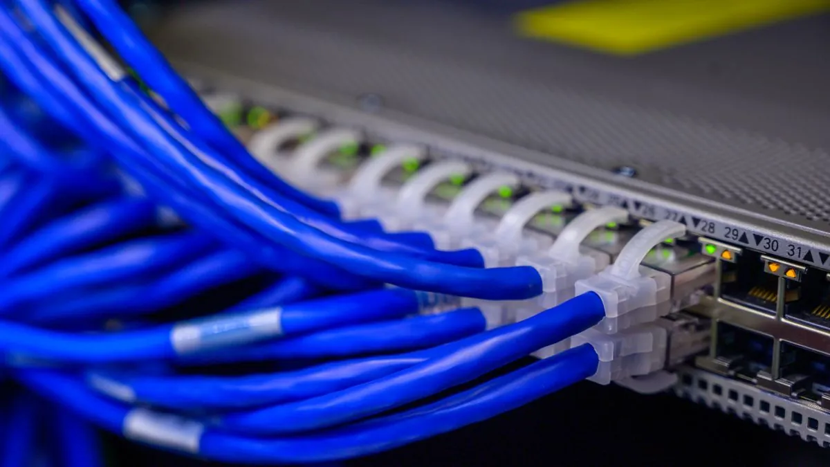
Why Grounding and Bonding Are Non-Negotiable in Data Centers
Every piece of equipment in a data center depends on a clean, low-impedance reference to earth. Servers, switches, GPU colocation racks, storage arrays, and UPS systems all assume that their chassis, signal shields, and power return paths share the same ground potential. When that assumption fails, the consequences range from intermittent bit errors and network packet corruption to catastrophic equipment damage from fault currents or lightning strikes.
Grounding and bonding are related but distinct disciplines. Grounding establishes a connection to the earth electrode system for safety and fault clearing. Bonding connects all conductive elements within the facility to the same equipotential plane, eliminating voltage differences that cause circulating currents, ground loops, and electromagnetic interference. A data center needs both, engineered as a unified system from the ground electrode up through every rack on the data hall floor.
The standards governing data center grounding have evolved significantly. TIA-607-D (Generic Telecommunications Bonding and Grounding for Customer Premises), IEEE 1100 (Recommended Practice for Powering and Grounding Electronic Equipment), and local electrical codes like NEC Article 250 all apply. Facilities designed for high-density colocation at 30 kW or more per rack face additional challenges that older grounding designs did not anticipate.
Ground Electrode Systems
Building the Earth Connection
The ground electrode system is the physical connection between the facility and the earth. For a data center, this typically consists of a ground ring encircling the building, supplemented by driven ground rods, concrete-encased electrodes (Ufer grounds), and connections to the building steel structural members.
A ground ring is a bare copper conductor (typically 2/0 AWG or larger) buried in direct contact with the earth at a minimum depth of 750 mm, running the perimeter of the building. Driven ground rods, typically 3-meter copper-clad steel rods, are installed at regular intervals around the ring and at building corners. The combined electrode system must achieve a ground resistance of 5 ohms or less, though many operators specify 1 ohm or less for critical data center facilities.
Soil resistivity varies enormously by geography and season. In arid regions like the UAE and Middle East, sandy soils can have resistivity exceeding 1,000 ohm-meters, making it difficult to achieve low ground resistance without extensive electrode systems. Chemical ground enhancement materials, deep-driven rods reaching moisture-retaining soil layers, or electrolytic ground rods may be required. Soil resistivity surveys (using the Wenner four-point method per IEEE 81) should be conducted before facility design to determine the electrode strategy.
Measuring Ground Electrode Resistance
Ground resistance is measured using the fall-of-potential method described in IEEE 81. This requires disconnecting the electrode under test from the building ground system and using a dedicated ground resistance tester with current and potential probes placed at specific distances from the electrode. The measurement must be performed at the correct probe spacing (62% of the distance to the current probe for a true reading) and repeated at multiple angles to verify consistency.
Clamp-on ground resistance testers offer a faster alternative for routine monitoring without disconnecting electrodes, but they measure the impedance of the entire ground loop rather than a single electrode, making them useful for trending but not for commissioning verification.
Telecommunications Main Grounding Busbar (TMGB)
The TMGB is the central grounding point for all telecommunications and data processing equipment in the facility. It is a copper busbar, typically 6 mm thick by 100 mm wide, mounted in the main equipment room or electrical room. The TMGB connects directly to the building ground electrode system, the AC power system ground (equipment grounding conductor from the service entrance), and the building structural steel ground.
All Tier-rated data centers should have a single TMGB that serves as the master grounding reference. In large campuses with multiple buildings, each building has its own TMGB bonded back to the campus master ground through bonding backbone conductors. The TMGB must be accessible for testing, inspection, and future connection additions, which means placing it behind locked racks or above inaccessible ceiling spaces is a design error.
Telecommunications Grounding Busbars (TGBs)
Placement and Sizing
Each data hall, telecommunications room, or mechanical room gets its own TGB. The TGB is bonded back to the TMGB through a dedicated bonding backbone conductor, typically a minimum 6 AWG copper conductor routed as directly as possible without splices. The TGB itself is a copper busbar sized to accommodate all current and anticipated future connections in that space.
For a typical data hall with 200 racks, the TGB should be sized to accommodate at least 250 lug connections (200 rack grounds plus cable tray bonds, PDU grounds, power distribution connections, and spare capacity). TGBs are typically mounted on insulated standoffs on a wall or structural column near the main cable tray entry point of the data hall.
Bonding Backbone Conductors
The bonding backbone conductor between each TGB and the TMGB is the critical link in the grounding hierarchy. TIA-607-D specifies a minimum of 6 AWG copper, but facilities with high-density GPU racks should consider upsizing to 3/0 AWG or larger to reduce impedance. The conductor should be continuous (no splices), routed away from sources of electromagnetic interference, and bonded to the building structural steel at each floor penetration.
In multi-story data centers, vertical bonding backbone conductors connect the TGBs on each floor back to the TMGB. These conductors should be bonded to the building steel at every floor they pass through to equalize potential during fault events and lightning strikes.
Bonding Network Topologies
Common Bonding Network (CBN)
A CBN is a mesh of conductive structural elements (building steel, metallic cable trays, conduit, raised floor pedestals, water pipes) that are all bonded together to form a low-impedance equipotential network. The CBN is unavoidable in any building with metallic structural elements, because these elements naturally form a de facto bonding network whether intentionally designed or not.
The key engineering decision is whether to rely on the CBN alone or to supplement it with a dedicated telecommunications bonding infrastructure. For data centers, relying solely on the CBN is insufficient because the impedance of structural connections varies with torque, corrosion, temperature, and time. Dedicated bonding conductors provide controlled, measurable, maintainable connections.
MESH-BN: Mesh Bonding Network
MESH-BN topology creates a deliberate mesh of bonding connections in the data hall floor. Every rack frame is bonded to its immediate neighbors, to the nearest cable tray section, and to the raised floor pedestals (if present). The result is a dense mesh where fault current and high-frequency noise have multiple parallel paths to the TGB, dramatically reducing ground impedance compared to a radial (star) topology.
MESH-BN is specified in EN 50310 and recommended by TIA-607-D for environments with high equipment density and high-frequency signal integrity requirements. GPU clusters operating at 400G and 800G line rates are exactly the environment where MESH-BN provides measurable benefit. The mesh topology reduces common-mode voltage between racks to millivolt levels, which matters when signal cables carry PAM4-encoded data sensitive to ground bounce.
Design consideration: MESH-BN requires significantly more copper conductor than a radial topology. A 200-rack data hall with MESH-BN uses approximately 2,000 to 3,000 meters of 6 AWG bonding conductor for the inter-rack mesh alone, compared to 600 to 800 meters for a radial design. The additional material cost is typically less than 0.5 percent of the overall data hall build cost but delivers measurable improvements in signal integrity and fault current handling.
Isolated Bonding Network (IBN)
An IBN is a single-point grounding topology where all equipment in a defined zone connects only to the TGB through dedicated, insulated bonding conductors. The equipment chassis is isolated from the CBN (structural steel, cable trays, raised floor). IBN is specified in TIA-607-D as an option for environments requiring maximum noise isolation, such as sensitive measurement equipment or broadcast studios.
In practice, maintaining true isolation in a high-density data center is extremely difficult. Every metallic cable, water pipe, and conduit entering the zone can defeat the isolation. For this reason, MESH-BN has largely replaced IBN as the preferred topology for modern data centers. IBN remains useful in specific laboratory or testing environments within a data center campus.
| Topology | Best For | Ground Impedance | Complexity |
|---|---|---|---|
| Radial (Star) | Small telecom rooms, low density | Higher | Low |
| CBN Only | General office spaces | Variable | Minimal |
| MESH-BN | High-density data halls, GPU clusters | Lowest | Medium |
| IBN (Isolated) | Sensitive labs, measurement rooms | Controlled | Highest |
Rack Grounding in High-Density Environments
Every rack in a data center must be bonded to the grounding system through a dedicated equipment bonding conductor. The conductor terminates at a lug point on the rack frame and runs to the nearest TGB or, in a MESH-BN topology, to the mesh bonding conductor serving that row.
For standard racks at 10 to 15 kW, a single 6 AWG bonding conductor per rack is adequate. High-density GPU racks at 40 kW or more should use two independent bonding conductors per rack, routed through different cable tray paths, to provide redundancy and reduce impedance. Both conductors should be accessible and marked for periodic torque verification.
Rack-to-rack bonding in a MESH-BN topology uses short copper bonding jumpers (typically 2 AWG flat braid) connecting adjacent rack frames through bolted or exothermic-welded connections. These jumpers create the lateral mesh that gives MESH-BN its low-impedance characteristic at high frequencies.
Raised Floor Grounding
If the data center uses a raised floor, every pedestal must be bonded to the grounding mesh. Raised floor pedestals are typically bonded using copper grounding straps from each pedestal base to a grounding grid conductor running under the floor. The grounding grid connects back to the TGB through multiple conductors at the perimeter of the data hall.
Bolted-stringer raised floor systems (where metal stringers connect pedestal heads) create a natural bonding network through the stringers. However, the resistance of bolted connections degrades over time due to vibration, thermal cycling, and oxidation. Supplemental bonding conductors should still be installed rather than relying solely on the stringer-to-pedestal contact.
Lightning Protection
Data center lightning protection consists of three elements: an air termination system (lightning rods or a mesh conductor on the roof), down conductors connecting the air terminals to the ground electrode system, and surge protective devices (SPDs) at every power and signal entry point.
The lightning protection system must be bonded to the building grounding system at the ground level. IEC 62305 and NFPA 780 both require this interconnection to prevent side-flash between the lightning system and the building ground during a strike. In regions with high lightning density like parts of the UAE and Gulf region, the lightning protection system design should be based on the Rolling Sphere Method at Protection Level I (20-meter sphere radius) for maximum coverage.
SPDs must be installed in a cascaded configuration: Type 1 (Class I) at the building service entrance, Type 2 (Class II) at distribution panels, and Type 3 (Class III) at the point of use near sensitive equipment. Each SPD connects to the grounding system through the shortest possible conductor (ideally less than 500 mm) to minimize inductance during a transient event.
Grounding for Liquid Cooling Systems
The rapid adoption of direct-to-chip liquid cooling and immersion cooling introduces new grounding requirements. Coolant distribution units (CDUs), pumps, heat exchangers, and metallic piping all become part of the conductive infrastructure that must be bonded.
Metallic cooling pipes carrying conductive coolant (typically water-glycol mixtures) can act as unintentional ground conductors, creating parallel paths for fault current. This is particularly problematic if the cooling system connects racks on different electrical panels, as the pipe can carry fault current between panels. Bonding every metallic section of the cooling piping to the nearest TGB or mesh bonding conductor eliminates this hazard.
Dielectric (non-conductive) coolants used in immersion cooling systems reduce but do not eliminate grounding concerns. The tank chassis, pump housings, heat exchanger shells, and any metallic fittings must still be bonded. Additionally, as dielectric fluids age or become contaminated, their resistivity can decrease, potentially making them marginally conductive.
Testing and Commissioning
Grounding system commissioning involves four categories of testing performed during the facility commissioning process:
- Ground electrode resistance: Fall-of-potential testing per IEEE 81 to verify the electrode system meets the design target (typically 1 to 5 ohms).
- Bonding continuity: Point-to-point resistance measurements between every TGB and the TMGB, and between every rack and its serving TGB. The resistance should be less than 0.1 ohms for each bonding conductor.
- Bolted connection torque: Every bolted grounding connection is verified to its specified torque value using a calibrated torque wrench. Under-torqued connections are the most common cause of grounding failures.
- Infrared thermography: Thermal imaging of all accessible grounding connections under load identifies hot spots caused by high-resistance connections that passed continuity testing but fail under current.
All test results should be documented in a grounding system as-built record and stored as part of the facility compliance documentation. This record becomes the baseline for annual retesting.
Common Grounding Mistakes in Data Centers
Even well-designed grounding systems fail when installation practices are poor. The most common mistakes include:
- Daisy-chaining rack grounds: Running a single bonding conductor from rack to rack in series rather than providing each rack with its own home run to the TGB. A single loose connection in a daisy chain disconnects every downstream rack.
- Using dissimilar metals without protection: Connecting copper conductors directly to aluminum bus or steel rack frames without bi-metallic lugs or joint compound creates galvanic corrosion that increases resistance over time.
- Routing bonding conductors alongside signal cables: Bonding conductors carrying fault current or lightning transients can induce voltage in adjacent signal cables. Maintain separation per TIA-569 and route bonding conductors in dedicated trays or conduit where possible.
- Failing to bond cable shields at both ends: Shielded data cables should have their shields bonded to the rack grounding point at both ends to prevent the shield from becoming an antenna for common-mode noise.
- Neglecting ongoing maintenance: Torqued connections loosen over years of thermal cycling and vibration. Without periodic retorque and testing, grounding resistance creeps upward until an equipment failure or safety event reveals the degradation.
Standards Reference
| Standard | Scope | Key Requirements |
|---|---|---|
| TIA-607-D | Telecom bonding and grounding | TMGB, TGB, bonding backbone, MESH-BN, IBN |
| IEEE 1100 (Emerald Book) | Powering and grounding electronic equipment | Single-point grounding, isolated ground circuits |
| NEC Article 250 | Grounding and bonding (US) | Electrode systems, conductor sizing, bonding |
| EN 50310 | Bonding networks (European) | CBN, MESH-BN, IBN topologies |
| IEEE 81 | Ground resistance measurement | Fall-of-potential method, soil resistivity |
| IEC 62305 | Lightning protection | Risk assessment, LPS design, SPD cascading |
Frequently Asked Questions
What is the difference between grounding and bonding in a data center?
Grounding creates a low-impedance path to earth for fault current and lightning energy. Bonding connects all metallic components to the same reference potential to eliminate voltage differences. Both are required: grounding handles safety and fault clearing, while bonding eliminates circulating currents and electromagnetic interference.
What is a Telecommunications Grounding Busbar (TGB)?
A TGB is a copper busbar installed in each data hall or telecom room that serves as the single-point grounding connection for all equipment in that space. Each TGB is bonded back to the main TMGB via a dedicated bonding conductor, typically a minimum of 6 AWG copper.
How often should data center grounding systems be tested?
Ground electrode resistance should be measured annually using a fall-of-potential test per IEEE 81. The target is typically 5 ohms or less, with many operators specifying 1 ohm or less. Bonding conductor continuity and torque checks should be performed every 12 months during scheduled maintenance.
What grounding topology is best for high-density GPU racks?
High-density GPU racks benefit from a MESH-BN topology, which connects every rack frame, cable tray section, and raised floor pedestal in a mesh pattern. This reduces ground impedance at high frequencies, minimizes common-mode noise, and provides multiple parallel paths for fault current. MESH-BN is specified in EN 50310 and recommended by TIA-607-D for high-density environments.
Does liquid cooling change data center grounding requirements?
Yes. Liquid cooling introduces metallic piping, CDUs, and manifolds that must be bonded to the grounding system. Even facilities using dielectric coolants must bond all metallic components. Coolant distribution units, pump housings, and metallic pipe segments should connect to the nearest TGB per TIA-607-D.
Design Your Data Center Power Infrastructure
Rax Data & Energy designs and operates data center facilities with fully engineered grounding and bonding systems meeting TIA-607-D, IEEE 1100, and local code requirements for mission-critical colocation and AI compute workloads.
Contact Us Rax Energy