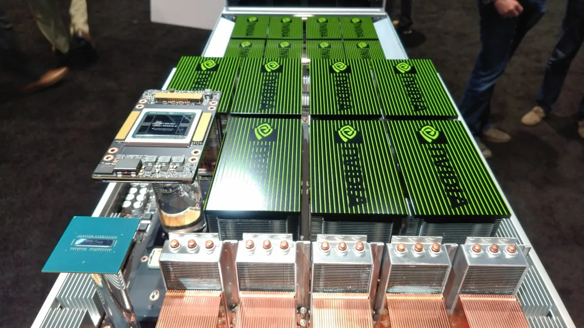
Deploying GPU servers in a colocation facility is a fundamentally different process from racking traditional enterprise IT equipment. GPU servers are heavier, draw significantly more power per rack unit, generate extreme heat density, often require liquid cooling connections, and depend on high-speed interconnects like InfiniBand that demand precise cable routing. A poorly executed rack and stack can result in thermal hotspots that throttle performance, power delivery problems that trip breakers under load, and network bottlenecks that waste expensive GPU compute cycles.
This guide walks through every phase of GPU server deployment in a colocation environment, from pre-deployment planning through commissioning and burn-in testing. Whether you are installing a single rack of GPU colocation servers or deploying a multi-rack AI training cluster, the principles and checklists below apply.
Pre-Deployment Planning
Site Readiness Assessment
Before any hardware ships to the colocation facility, verify that the site can actually support your deployment. GPU servers impose requirements that many standard colocation spaces do not meet. The assessment should confirm:
- Power availability: Confirm that the allocated circuits provide sufficient amperage and voltage for your full deployment at peak load. A rack of four 8-GPU servers (H100 SXM) requires approximately 40 to 45 kW. Verify that the power distribution units in the rack can handle the total load, including any networking switches and top-of-rack equipment.
- Cooling capacity: Confirm that the facility has provisioned cooling for the heat load your racks will generate. At 40+ kW per rack, direct liquid cooling or rear-door heat exchangers are typically required. The coolant distribution units (CDUs) must be installed, plumbed, and tested before your hardware arrives.
- Floor loading capacity: A fully loaded GPU rack can weigh 400 to 600 kg. Standard raised floors rated at 150 lbs per square foot cannot safely support this. Verify the floor rating at your specific rack location, not just the facility specification, as loading capacity can vary across the data hall.
- Network cross-connects: Confirm that fiber cross-connects to your upstream provider or IX are active and tested. For multi-rack deployments requiring InfiniBand, verify that the InfiniBand fabric switches and cabling paths are provisioned.
Rack Layout and Space Planning
GPU server rack layouts require more deliberate planning than enterprise IT racks because of the power density and airflow requirements involved:
| Component | Typical Rack Units | Weight (approx.) | Power Draw |
|---|---|---|---|
| 8-GPU Server (H100 SXM) | 6U to 8U | 60-75 kg | 10-10.5 kW |
| InfiniBand NDR Switch | 1U | 10-15 kg | 0.3-0.5 kW |
| Ethernet Top-of-Rack Switch | 1U | 8-12 kg | 0.15-0.3 kW |
| Power Distribution Unit (PDU) | 0U (vertical mount) | 5-10 kg | Metering only |
| Cable Management Panel | 1U to 2U | 1-2 kg | None |
Plan the vertical layout so that the heaviest servers occupy the bottom of the rack to lower the center of gravity. Leave adequate spacing between servers for airflow if using air cooling, or for liquid cooling manifold connections if using direct-to-chip cooling. Reserve the top 4 to 6 rack units for networking switches and cable management.
Shipping and Receiving
GPU servers are high-value, fragile equipment. Coordinate with the colocation facility on their receiving procedures:
- Delivery scheduling: Most facilities require advance notice for large deliveries and have specific receiving hours. Schedule delivery during staffed hours so equipment can be immediately moved to a secure staging area.
- Inspection protocol: Inspect every box for shipping damage before signing delivery receipts. Photograph any visible damage to packaging. Open and inspect servers within 48 hours of delivery to identify internal damage while freight claims are still straightforward.
- Staging area: Request a staging area where you can unbox, inspect, and prepare servers before racking them. This is especially important for liquid cooling deployments where coolant manifold fittings must be attached before the server enters the rack.
Physical Installation
Rail Mounting and Server Installation
GPU server rail kits differ from standard 1U server rails. Many GPU servers use tool-less snap-in rails, but at 60 to 75 kg per server, the mechanical tolerances matter more than with lighter equipment:
- Install inner rails on the server: Attach the inner rail segments to both sides of the server chassis using the manufacturer's provided screws or snap-in clips. Verify that the rail position aligns with the server's screw holes — misalignment causes binding during insertion.
- Mount outer rails in the rack: Secure the outer rails to the front and rear rack posts using cage nuts and bolts or the tool-less mounting clips provided. Use a level to verify that both rails are at the same height and horizontal. Even a few millimeters of misalignment can make a 70 kg server difficult to slide in.
- Slide the server into the rack: This typically requires two people for heavy GPU servers. Lift the server to rail height, align the inner rails with the outer rail channels, and slide the server in smoothly. Do not force it. If it binds, withdraw and check rail alignment.
- Secure the server: Once fully inserted, secure the server to the front rack posts using the provided thumbscrews or captive screws. This prevents the server from sliding out during cable connections or maintenance.
Safety note: Always use a mechanical server lift for GPU servers above 30 kg. Manual lifting of heavy servers into elevated rack positions creates serious risk of injury and equipment damage. Most colocation facilities have lifts available or can provide one upon request.
Power Connections
GPU servers typically have redundant power supply units (PSUs) rated at 2,000 to 3,000 watts each. For full redundancy, connect each PSU to a separate PDU fed from a different power circuit:
- Verify circuit capacity: Before connecting the first server, check the PDU's current draw reading. Confirm that adding your server will not exceed 80 percent of the circuit breaker rating. Running circuits above 80 percent load in a continuous-duty application violates electrical code in most jurisdictions and risks nuisance trips.
- Use the correct power cord: GPU servers require high-amperage power cords, typically C19/C20 connectors for servers drawing over 10 amps per PSU. Do not use standard C13/C14 cords on high-power servers — they are rated for lower current and will overheat.
- Verify redundancy: After connecting both PSUs, confirm that each is drawing power by checking the PSU status LEDs. Then test failover by disconnecting one PDU and confirming the server continues operating on the remaining power supply without interruption.
- Label everything: Label each power cable with the server name, PSU position (A/B), and the PDU outlet number. This documentation is critical for remote hands technicians who may need to power-cycle specific servers at your direction.
Liquid Cooling Connections
For deployments using direct-to-chip liquid cooling, the coolant connections add complexity to the rack and stack process:
- Pre-install coolant manifolds: In-rack manifolds that distribute coolant from the CDU to individual servers should be installed before the servers are racked. Retrofitting manifolds around installed servers is significantly more difficult.
- Connect server quick-disconnect fittings: Each liquid-cooled server has supply and return quick-disconnect (QD) fittings. Connect these to the corresponding manifold ports. Verify orientation — supply and return lines are not interchangeable and connecting them in reverse will severely reduce cooling effectiveness.
- Leak testing: After connecting all fittings, perform a leak test by pressurizing the loop to the manufacturer-specified test pressure (typically 1.5 to 2 times operating pressure) and holding for 15 to 30 minutes while inspecting every joint. Even a minor drip near high-value GPU hardware is unacceptable.
- Flow verification: Confirm that coolant flow rates through each server meet the minimum specification, typically measured at the CDU or via flow sensors in the manifold. Insufficient flow causes localized overheating even when the cooling system appears to be functioning.
Network Cabling
Management Network
Every GPU server has a baseboard management controller (BMC or IPMI) that provides out-of-band management access. Connect the BMC port to a dedicated management network before doing anything else — this allows remote access for firmware updates, BIOS configuration, and troubleshooting even when the server's operating system is not running.
Data Network (Ethernet)
Standard Ethernet connectivity provides operating system management, storage access, and general network traffic. For GPU servers, this is typically 25 GbE or 100 GbE connections to a top-of-rack switch:
- Use fiber optic cables (typically OM4 multimode for distances under 100 meters within the facility) with appropriate transceivers.
- Test every link after installation using a fiber light source and power meter, or by confirming link-up status on the switch port.
- Follow cable management best practices — dress cables neatly in the cable management trays, maintain minimum bend radius on fiber, and label both ends of every cable with source and destination.
High-Speed Interconnect (InfiniBand)
For multi-node AI training clusters, InfiniBand or RoCE networking provides the low-latency, high-bandwidth interconnect required for efficient gradient synchronization. InfiniBand cabling is more demanding than Ethernet:
- Cable types: InfiniBand NDR uses either passive copper cables (up to 2 meters), active optical cables (AOCs, up to about 30 meters), or fiber cables with separate transceivers. Choose based on the distance between your GPU servers and the InfiniBand switches.
- Port mapping: In a multi-rail network fabric, each GPU server connects to multiple InfiniBand switches across different rails. Create a port map before cabling that specifies exactly which server port connects to which switch port on which rail.
- Testing: After cabling, verify all InfiniBand links are up at the expected data rate (NDR 400 Gbps) using switch management tools. Run a quick NCCL all-reduce benchmark across the cluster to confirm that inter-node communication bandwidth matches expectations before declaring the network ready for production workloads.
Commissioning and Burn-In
Initial Power-On and BIOS Configuration
With all physical connections complete, power on the servers sequentially rather than simultaneously. Bringing all servers online at once creates a massive inrush current that can trip upstream breakers. A staggered power-on, spacing each server by 30 to 60 seconds, allows the electrical infrastructure to absorb the load gradually.
After power-on, access each server's BMC interface and configure:
- Boot order (network PXE boot for automated OS provisioning or local disk)
- Memory speed and error correction settings
- PCIe slot configuration to ensure all GPUs are recognized
- Fan profile (if applicable — some GPU servers have configurable fan curves)
- Power capping limits if you need to stay within a specific power budget per server
Firmware and Driver Updates
Before running any workloads, update all firmware to the latest validated versions. GPU server firmware stacks typically include:
- BMC/IPMI firmware
- BIOS/UEFI firmware
- GPU firmware (vBIOS for NVIDIA GPUs)
- NIC firmware (ConnectX for InfiniBand or Ethernet)
- Storage controller firmware (NVMe drive firmware)
Use the server manufacturer's firmware update tools to apply all updates in the correct order. Some firmware updates require specific sequencing to avoid compatibility issues. After updates, verify that all components are recognized at their expected specifications using diagnostic tools like nvidia-smi for GPUs and ibstat for InfiniBand HCAs.
Burn-In Testing
Burn-in testing validates that every component functions correctly under sustained load and identifies infant failures before the equipment enters production. A thorough GPU server burn-in runs for 24 to 72 hours and includes:
- GPU stress test: Run a sustained compute workload (such as a matrix multiplication loop or a standard GPU benchmark suite) on all GPUs simultaneously for 24 to 48 hours. Monitor for GPU memory ECC errors, thermal throttling, and any GPU falling off the PCIe bus.
- Memory test: Run a full memory pass across all system RAM. Memory errors during burn-in indicate modules that should be replaced before production use.
- Storage test: Run sequential and random I/O tests across all NVMe drives to verify rated read and write throughput and identify drives with early-life failures.
- Network test: Run sustained throughput tests on all Ethernet and InfiniBand links simultaneously to verify that all ports achieve their rated bandwidth without errors.
- Thermal stability: During the burn-in, monitor inlet and exhaust air temperatures (or coolant supply and return temperatures for liquid-cooled systems) to confirm that the cooling system maintains safe operating conditions under full load. If any server shows thermal throttling during burn-in, the cooling is insufficient and must be addressed before production deployment.
Deployment tip: Document the burn-in results for every server, including serial numbers, firmware versions, benchmark scores, and any replaced components. This baseline documentation is invaluable for troubleshooting performance issues later and for warranty claims if hardware fails after deployment. The commissioning and acceptance testing guide provides additional context on facility-level validation.
Post-Deployment Checklist
After physical installation, cabling, and burn-in are complete, run through this final verification before handing the deployment over to the operations team:
- All servers visible in BMC/IPMI management interface with correct asset tags and IP assignments
- All GPUs detected by the OS and reporting correct memory and compute capability via
nvidia-smi - All network links (management, data, InfiniBand) showing link-up at expected speed with zero errors
- Power draw per rack matches expected load within 10 percent — significant deviation indicates a misconfigured or failed component
- Cooling metrics (temperature, coolant flow rate) stable under full load for at least 4 hours
- All power cables, network cables, and cooling connections labeled at both ends
- Rack elevation diagram updated and provided to the colocation provider for their records
- Remote access confirmed from outside the facility (BMC, SSH, and application-level access all functional)
- Emergency contact list and escalation procedures exchanged with the facility operations team
Common Deployment Pitfalls
Based on real-world GPU colocation deployments, these are the issues that most frequently cause delays or require rework:
- Undersized power circuits: The quoted power per rack and the actual circuit capacity sometimes diverge. A 40 kW allocation does not help if it is delivered across circuits that individually cap at 5.7 kW (30A at 208V, derated to 80 percent). Verify the per-circuit capacity, not just the total allocation.
- Cooling capacity shortfalls: Facility cooling that handles the design load on paper may struggle when the actual heat load concentrates in a few dense racks rather than spreading across many low-density ones. If your racks are significantly denser than the facility average, confirm that the local cooling is sized for your specific zone.
- Fiber cable length errors: Pre-ordered fiber patch cables that are too short to reach the patch panel or too long to manage neatly. Measure actual cable paths, including vertical runs through cable trays, before ordering. Add 1 to 2 meters of slack to each measurement.
- Missing PDU types: Arriving at the facility to discover that the installed PDUs have C13 outlets when your servers need C19, or three-phase 400V PDUs when your servers expect single-phase 208V. Confirm PDU specifications as part of the site readiness assessment.
- Incomplete BMC networking: Forgetting to connect or configure BMC ports, then losing the ability to manage servers remotely when the OS is unresponsive. BMC connectivity should be the first network connection made and the first one tested.
Frequently Asked Questions
How long does it take to rack and stack GPU servers in a colocation facility?
Physical installation of a single GPU server rack typically takes 4 to 8 hours, covering mechanical mounting, power connections, network cabling, and liquid cooling hookup if applicable. Full commissioning including burn-in testing, firmware updates, OS installation, and workload validation adds another 1 to 3 days per rack. A multi-rack deployment of 8 to 16 racks can usually be completed in 1 to 2 weeks with a dedicated deployment team.
What tools are needed for GPU server rack and stack?
Standard tools include cage-nut insertion tools, Phillips and Torx screwdrivers, a torque wrench for rail mounting, a cable management kit with hook-and-loop straps, a power meter or clamp ammeter for verifying circuit loads, a fiber light source and power meter for testing optical cables, and a laptop with serial console cable and BMC access software. For liquid cooling deployments, also bring a coolant pressure gauge and leak detection strips.
How much does a GPU server weigh for rack planning?
An 8-GPU server such as a DGX H100 weighs approximately 60 to 75 kg (130 to 165 lbs). A fully loaded 42U rack with 4 GPU servers, networking equipment, and PDUs can weigh 400 to 600 kg (880 to 1,320 lbs). This exceeds the floor loading capacity of many standard raised floors. GPU-ready colocation facilities typically have reinforced flooring rated for 300 lbs per square foot or higher.
Do I need liquid cooling to deploy GPU servers in colocation?
It depends on rack density. Air-cooled deployments work for racks up to approximately 30 to 40 kW. Above 40 kW per rack, or when deploying high-density racks with H100 SXM GPUs or newer at full density, liquid cooling becomes necessary. NVIDIA GB200 NVL72 racks require liquid cooling by design and cannot operate with air cooling alone.
Can my colocation provider handle the rack and stack for me?
Most colocation providers offer rack and stack as either an included onboarding service or an optional paid service. Provider-managed deployment is often preferable because their technicians know the facility infrastructure, power panel assignments, and airflow patterns. Verify that the provider carries insurance covering equipment damage during installation.
Deploy GPU Infrastructure at Rax
Rax Data & Energy provides turnkey GPU colocation with pre-provisioned power, liquid cooling, and professional rack and stack services — from single-rack pilot deployments to multi-megawatt AI clusters.
Contact Us AI Compute Solutions