Data Center Cable Management Standards and Best Practices: TIA-942 and BICSI Guide
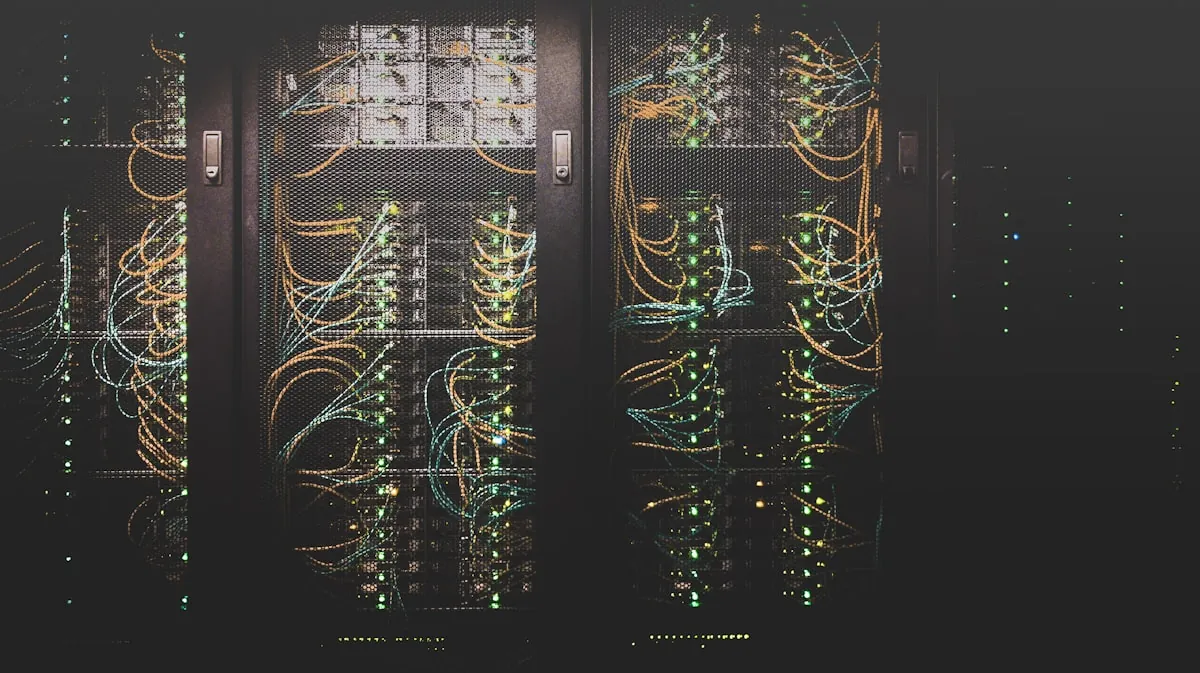
Poor cable management is one of the fastest ways to turn a well-designed data center into an operational nightmare. Tangled cables block airflow and increase cooling costs, unmanaged pathways make troubleshooting impossible, and undocumented infrastructure creates single points of failure that nobody can identify until they fail. This guide covers the standards, engineering principles, and practical techniques that separate professionally managed cabling infrastructure from the kind that ends up on data center horror show websites.
The Standards Framework
TIA-942: The Foundation
ANSI/TIA-942 (Telecommunications Infrastructure Standard for Data Centers) defines the cabling topology, pathway requirements, and performance specifications for data center structured cabling systems. The standard establishes a hierarchical architecture with clearly defined functional areas:
- Entrance Room (ER): Where outside plant cabling and service provider connections terminate. Demarcation point between building cabling and carrier infrastructure.
- Main Distribution Area (MDA): The central point of the structured cabling system. Houses core network switches, routers, and the main cross-connect. All other functional areas connect here.
- Horizontal Distribution Area (HDA): Intermediate distribution point serving a group of equipment cabinets. Houses access layer switches and horizontal cross-connects.
- Equipment Distribution Area (EDA): The cabinet rows where servers, storage, and network equipment are installed. Horizontal cabling terminates at patch panels in or adjacent to these cabinets.
- Zone Distribution Area (ZDA): Optional consolidation point between the HDA and EDA that provides flexibility for reconfiguration without disrupting the permanent horizontal cabling.
This hierarchical model matters because it separates permanent cabling infrastructure (backbone and horizontal runs that are designed to last 15-20 years) from equipment connections (patch cables that change with every server deployment or migration). When the hierarchy is properly implemented, equipment changes require only patch cable modifications while the permanent infrastructure remains undisturbed.
BICSI TDMM and Data Center Design Manual
The BICSI Telecommunications Distribution Methods Manual (TDMM) and Data Center Design Manual (DCDM) complement TIA-942 with detailed engineering guidance on pathway sizing, cable management hardware selection, installation practices, and testing procedures. While TIA-942 defines what the infrastructure should look like, BICSI publications explain how to engineer and install it. Key BICSI guidance includes cable tray fill calculations, vertical riser design loads, fire stopping requirements, and quality assurance testing procedures.
ISO/IEC 24764
The international equivalent to TIA-942, ISO/IEC 24764 defines data center cabling infrastructure requirements for global installations. For facilities in the UAE and GCC region, ISO/IEC standards are often specified by authorities having jurisdiction alongside or in place of TIA standards. The technical requirements are substantially similar, but channel length calculations and testing parameters have minor differences that must be accounted for in specification documents.
Pathway Design and Cable Tray Engineering
Overhead Cable Tray Systems
Modern data centers overwhelmingly use overhead cable tray systems rather than under-floor pathways. The reasons are practical: raised floor space is increasingly needed for liquid cooling distribution, under-floor cables impede airflow in pressurized plenum designs, and overhead trays provide better accessibility for maintenance and adds/moves/changes.
Cable tray sizing follows NEC Article 392 and NEMA VE 1/VE 2 standards. The critical design parameters are:
| Parameter | Design Standard | Practical Guidance |
|---|---|---|
| Fill Ratio (initial) | NEC 392.22: max 50% for signal cables | Target 30-40% at deployment to leave growth room |
| Fill Ratio (ultimate) | Plan for full build-out population | Never exceed 60% even at full capacity |
| Tray Width (standard row) | 12" (300mm) minimum per TIA-942 | 18-24" (450-600mm) for high-density environments |
| Separation: Power/Data | TIA-942: 12" (300mm) minimum | Use separate tray systems with physical barrier preferred |
| Vertical clearance | Minimum 12" between tray tiers | 18" preferred for maintenance access |
| Load rating | NEMA VE 1 load class specifications | Size for ultimate cable weight plus 25% safety factor |
| Bend radius | TIA-942: 10x cable OD for UTP, 15x for fiber | Use sweep fittings; never force cables around corners |
Hot Aisle / Cold Aisle and Cabling
Cabling design must integrate with the facility's thermal management strategy. In hot aisle containment configurations, overhead cable trays running above the hot aisle must not block return air pathways to ceiling-mounted CRAH units. Cable trays above the cold aisle should not impede supply air distribution. In facilities with rear-door heat exchangers or in-row cooling, cable routing must accommodate coolant piping that shares the overhead space.
The practical impact is significant: a cable tray loaded to 70% fill at the top of a hot aisle can increase exhaust air temperature by 2-4 degrees Celsius by restricting convective flow, directly impacting cooling energy consumption. This is one of the engineering reasons -- beyond pure cable management cleanliness -- that fill ratios must be controlled.
Structured Cabling Architecture for High-Density Compute
End-of-Row vs Top-of-Rack Switching
The choice between end-of-row (EoR) and top-of-rack (ToR) network architecture has profound implications for cable management. ToR architectures place access switches in every cabinet, requiring only short patch cables within the cabinet but necessitating fiber uplinks from every cabinet back to aggregation switches. EoR architectures consolidate switches at the end of each row, requiring longer copper horizontal cables from each server cabinet to the switch cabinet but fewer fiber uplinks overall.
For standard compute deployments at 5-15 kW per cabinet, both approaches work. For high-density GPU deployments at 30-100+ kW per cabinet where each server may require multiple 100 GbE or 400 GbE connections, ToR switching with leaf-spine fabric is the dominant architecture. The cable management challenge shifts from copper horizontal runs to managing high-density fiber patches within each cabinet and maintaining organized fiber trunks to spine switches.
Fiber Trunk and Breakout Cabling
Pre-terminated fiber trunk cables with MPO/MTP connectors have become the standard for data center backbone cabling. A single MPO-24 trunk cable replaces twelve individual LC-duplex fiber patches, dramatically reducing cable volume and simplifying pathway management. Trunk cables are manufactured with precise lengths and factory-tested, eliminating field termination quality variations.
For high-performance computing fabrics using 400 GbE (8-fiber QSFP-DD transceivers) or InfiniBand HDR/NDR, the fiber count per cabinet can reach 96-192 fibers for a fully populated switch. Pre-terminated MPO trunk systems with breakout cassettes at each end provide the cleanest path management while maintaining the insertion loss budgets required for these high-speed links.
Intra-Cabinet Cable Management
The most visible and most frequently neglected aspect of cable management is what happens inside the cabinet. Best practices for intra-cabinet management include:
- Vertical cable managers: Zero-U or tool-less vertical managers on both sides of every cabinet. These should be sized for the maximum cable population the cabinet will support, not current deployment. A 42U cabinet fully populated with 1U servers generates approximately 84 network cables plus power cables -- the vertical managers must accommodate this.
- Horizontal cable organizers: 1U or 0.5U horizontal managers between every two to three equipment units. These prevent cables from dangling across equipment fronts, which blocks airflow and creates maintenance hazards. In practice, horizontal managers consume 20-25% of usable rack units in a fully managed cabinet.
- Slack management: Every patch cable has excess length. Without dedicated slack management (service loops, slack spools), excess cable accumulates as tangles. Route excess cable through horizontal managers and secure with hook-and-loop fasteners (never cable ties -- they damage cable jackets and cannot be adjusted).
- Color coding: A consistent color scheme for patch cables dramatically improves troubleshooting speed. Common schemes use color to distinguish network type (management vs. production vs. storage), VLAN assignment, or redundancy path (A-side vs. B-side). Document the color scheme and enforce it as a configuration standard, not a suggestion.
- Cable length selection: Specify patch cables in the precise length needed for each connection. Using 3-meter cables for 0.5-meter connections creates 2.5 meters of excess cable per connection that must be managed. Across thousands of connections, this excess becomes unmanageable. Maintain stock of cables in 0.3m, 0.5m, 1m, 1.5m, 2m, and 3m increments and select the shortest cable that reaches comfortably without strain.
Labeling Standards and Documentation
TIA-606 Labeling Standard
ANSI/TIA-606 defines labeling standards for telecommunications infrastructure at four levels of detail (Class 1 through Class 4). Data centers should implement Class 3 or Class 4 labeling, which requires unique identifiers for every cable, pathway, termination point, cabinet, and functional area, with records maintained in a centralized database.
A practical labeling scheme for data center cables includes the source room or area, source cabinet or panel, source port, destination room or area, destination cabinet or panel, and destination port. Labels should be machine-printed (never handwritten), applied at both ends of every cable, and include the same identifier on the cable itself at intervals for identification in pathways.
DCIM Integration
Cable documentation must integrate with the facility's DCIM system to provide a single source of truth for physical connectivity. Every port-to-port connection should be tracked in the DCIM database with fields for cable type, length, installation date, connected equipment, circuit identifier, and operational status. This documentation enables automated impact analysis (identifying which customers are affected by a specific cable pathway failure), capacity planning (showing available ports and pathway space), and compliance auditing (demonstrating physical redundancy for colocation SLA requirements).
Power Cabling Considerations
Separation Requirements
TIA-942 and NEC Article 800 require physical separation between power and telecommunications cables to prevent electromagnetic interference. The minimum separation for unshielded data cables parallel to power cables is 12 inches (300mm). When cables must cross, they should do so at 90-degree angles where the coupling length is minimized.
In practice, data centers should route power and data in completely separate cable tray systems. The power trays typically run along one axis (following the power whip drops from overhead busways or PDUs) while data trays run perpendicular or on a different tier. This separation eliminates EMI concerns and simplifies maintenance by keeping different disciplines in different physical spaces.
High-Power Density Environments
In GPU-intensive environments drawing 40-100 kW per cabinet, power cabling volume can exceed data cabling volume. A cabinet drawing 60 kW at 208V three-phase requires approximately 170A per phase, which may mandate multiple power whips per cabinet, each using 4/0 AWG or larger conductors. These heavy-gauge power cables are rigid and heavy, requiring substantial cable tray support and wider bend radii than typical data cables. The pathway engineering for power distribution in high-density zones must be coordinated with data cable pathways to prevent conflicts in the limited overhead space.
Cable Management for Colocation Environments
Multi-Tenant Separation
Colocation facilities face unique cable management challenges because multiple tenants share common pathways. Physical separation of tenant cabling prevents accidental disconnection, simplifies troubleshooting, and provides the security boundary that zero trust principles require. Best practices include dedicated vertical cable managers or dedicated sections within shared managers for each tenant, different colored cable trays or tray sections per tenant zone, individually locked patch panel housings where cross-connects terminate, and strict change management procedures that require escorted access for any work in shared pathways.
Cross-Connect Management
In colocation environments, cross-connects between tenants and between tenants and carriers are the most critical and most frequently changed connections. Dedicated cross-connect panels in the MDA or meet-me room should be organized by tenant with clear labeling, documented in the DCIM system, and protected by physical access controls. The cross-connect area is where sloppy cable management creates the most operational risk because a single misdirected or accidentally disconnected cross-connect can take down a customer's connectivity.
Testing and Quality Assurance
Copper Testing
Every copper channel must be tested to the performance standard it was designed for (Category 6A, Category 8, etc.) using a Level III or Level IV field tester. Permanent link or channel testing must verify insertion loss, return loss, near-end crosstalk (NEXT), power sum NEXT, alien crosstalk (for 10GBASE-T and above), and propagation delay. Test results must be stored in electronic format linked to cable identifiers in the documentation system.
Fiber Testing
Fiber infrastructure requires two types of testing: insertion loss testing (using a light source and power meter or OLTS) to verify that each link meets the loss budget for the intended application, and OTDR testing to characterize the fiber plant and identify splice points, connectors, bends, and potential failure points along the route. For MPO trunk cables, every fiber must be tested individually. Factory test results should be verified against field measurements to confirm that no damage occurred during installation.
Ongoing Validation
Cable management is not a one-time installation activity. Facilities should implement periodic audits -- quarterly for critical infrastructure, annually for general cabling -- that verify cable tray fill levels, labeling accuracy and legibility, abandoned cable identification, pathway integrity (no sagging trays, missing supports, or fire stop breaches), and compliance with the documented standards. Infrared scanning of cable pathways and termination points identifies hot spots that may indicate loose connections, overloaded circuits, or cables operating beyond their rated current capacity.
Future-Proofing Cable Infrastructure
The most expensive cable management mistake is designing for today's needs. Data center cabling infrastructure should be designed for a minimum 15-year lifecycle, during which network speeds will increase by at least two to three generations. Practical future-proofing strategies include:
- Singlemode fiber everywhere: Singlemode fiber supports all current and foreseeable ethernet speeds (up to 800 GbE and beyond) over data center distances. The marginal cost premium over multimode OM4/OM5 is small and is offset by eliminating the risk of a fiber plant that cannot support the next speed upgrade. Singlemode transceivers have reached price parity with multimode at 100 GbE and below.
- Oversized pathways: Cable trays should be sized for projected full build-out plus a 25% safety margin. Adding cable tray capacity after a facility is operational requires working over live equipment, which is expensive, disruptive, and risky.
- Modular patch panels: Use patch panel systems that support cassette or adapter plate changes without replacing the panel housing. This allows upgrading from LC to CS connectors (for 800 GbE) or from MPO-12 to MPO-16 configurations without structural changes.
- Separate data and storage fabrics: Even if current architecture uses converged networking, maintaining pathway separation for compute networking and storage networking (or InfiniBand GPU fabric) provides the physical flexibility to deploy dedicated storage fabrics or GPU interconnects in the future without pathway congestion.
Common Mistakes and How to Avoid Them
- Using cable ties instead of hook-and-loop: Cable ties cannot be adjusted without cutting, damage cable jackets, and create maintenance nightmares. Use hook-and-loop wraps exclusively.
- Not tracking abandoned cables: Over time, decommissioned equipment leaves behind cables that nobody removes because nobody knows if they are in use. Every cable removal must be tracked in the documentation system. Schedule annual abandoned cable audits and removal campaigns.
- Mixing copper and fiber in the same organizer: Copper cables are heavier and stiffer than fiber and can crush or kink fiber when they share tight spaces. Use separate organizers or dedicated sections within organizers.
- Ignoring bend radius: Every cable has a minimum bend radius specified by the manufacturer. Exceeding it degrades performance (increased insertion loss for copper, microbending loss for fiber) and can cause intermittent failures that are extremely difficult to diagnose.
- Under-specifying intra-cabinet management: The most common complaint from operations teams is insufficient space for cable management within cabinets. Specify full-depth vertical managers and budget the rack units for horizontal organizers during the design phase, not as an afterthought.
World-Class Infrastructure Starts with the Cables
Rax facilities are built to TIA-942 Rated-3 cabling standards with pre-terminated fiber trunk infrastructure, comprehensive labeling per TIA-606, and cable management designed for high-density GPU and AI workloads from day one.
Tour Our Facilities