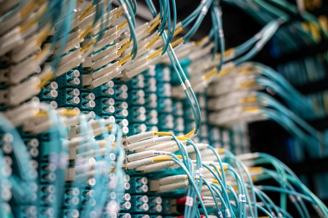
Key takeaway: Structured cabling is the nervous system of every data center. A well-designed cabling plant based on TIA-942 standards supports multiple generations of network equipment without rip-and-replace upgrades. For high-density AI and GPU facilities operating at 100 GbE to 800 GbE per port, fiber optic infrastructure decisions made during initial build-out determine whether future bandwidth upgrades require only transceiver swaps or complete recabling -- a difference of days versus months and orders of magnitude in cost.
Why Structured Cabling Matters More in High-Density Environments
Data centers have historically treated cabling as an afterthought -- something installers figure out after the racks, power, and cooling are designed. In traditional enterprise environments with 5 to 10 kW per rack, this approach works adequately because cable volumes are manageable and bandwidth requirements are modest.
High-density environments change the equation. A single GPU rack drawing 40 to 100 kW may require 32 or more high-speed fiber connections for compute fabric, additional fiber for storage networking, copper for management, and multiple high-amperage power cables. When a facility houses hundreds of such racks, the cabling plant becomes one of the most complex and failure-prone infrastructure systems in the building.
Poor cabling decisions create cascading problems: insufficient pathway space causes cable congestion that blocks airflow, excessive bend radius violations in fiber cause signal loss and link errors, inadequate labeling turns troubleshooting a single bad cable into a multi-hour exercise, and using the wrong fiber grade limits future speed upgrades. These problems compound over time as equipment refreshes add cables without removing old ones.
TIA-942 Cabling Topology
The TIA-942 standard (Telecommunications Infrastructure Standard for Data Centers) defines a hierarchical cabling topology that separates the data center into functional areas, each with specific cabling roles.
Functional Areas
Entrance Room (ER): Where external service provider cables enter the building. Contains demarcation points for carrier circuits, cross-connects to the main distribution area, and often houses carrier-provided equipment. The ER should be physically separated from the main data hall for security and to isolate external cabling from internal infrastructure.
Main Distribution Area (MDA): The central point of the cabling topology. Core network switches and routers reside here. All backbone cabling from the ER, horizontal distribution areas, and zone distribution areas terminates in the MDA. In large facilities, the MDA may be a dedicated room or a designated area within the data hall.
Horizontal Distribution Area (HDA): Houses aggregation or distribution layer switches that serve a group of equipment racks. Each HDA serves a defined zone of the data hall. The HDA-to-rack connection is the horizontal cabling segment, typically the most numerous cabling runs in the facility.
Equipment Distribution Area (EDA): The racks and cabinets containing servers, storage, and other end equipment. Horizontal cables from the HDA terminate at patch panels or directly at equipment ports in the EDA.
Zone Distribution Area (ZDA): An optional consolidation point between the HDA and EDA. ZDAs are useful in modular and prefabricated data center designs where pre-terminated trunk cables run to a consolidation point, and shorter patch cables connect from there to individual racks.
Backbone vs. Horizontal Cabling
TIA-942 distinguishes between backbone cabling (ER-to-MDA, MDA-to-HDA) and horizontal cabling (HDA-to-EDA). Backbone cabling typically uses single-mode fiber for long runs and high bandwidth. Horizontal cabling uses either multimode fiber or copper depending on speed requirements and distance.
The standard recommends a maximum distance of 300 meters for backbone cabling using single-mode fiber and 90 meters for horizontal cabling using copper (Category 6A). These distances include a 5-meter equipment cord allowance at each end, making the actual permanent link distance shorter.
Fiber Optic Cabling: Media Selection
Fiber optic cabling carries the vast majority of data traffic in modern data centers. Selecting the right fiber grade is one of the most consequential infrastructure decisions because the fiber plant typically has a 15 to 25 year useful life -- far longer than the networking equipment connected to it.
Multimode Fiber Grades
| Fiber Grade | Core Size | Bandwidth (EMB) | 10 GbE Reach | 100 GbE Reach | 400 GbE Reach |
|---|---|---|---|---|---|
| OM3 | 50 um | 2000 MHz*km | 300 m | 70 m (SR4) | 50 m (SR4.2) |
| OM4 | 50 um | 4700 MHz*km | 400 m | 100 m (SR4) | 100 m (SR4.2) |
| OM5 | 50 um | 4700 MHz*km (850nm), 2470 MHz*km (953nm) | 400 m | 100 m (SR4), 150 m (SWDM) | 100 m (SR4.2) |
OM3 is the baseline laser-optimized multimode fiber. It remains adequate for 10 GbE runs under 300 meters but struggles with 100 GbE distances in larger data halls. For new installations, OM3 offers limited future-proofing and is generally not recommended.
OM4 is the most widely deployed fiber grade in data centers built since 2015. It supports 100 GbE (100GBASE-SR4) up to 100 meters -- sufficient for most data hall horizontal runs. OM4 represents the best balance of cost and capability for the current generation of networking equipment.
OM5 (wideband multimode fiber) adds support for shortwave wavelength division multiplexing (SWDM), which allows multiple wavelengths (850nm to 953nm) over a single fiber pair. This can reduce fiber strand count for certain transceiver types. However, OM5 carries a premium and the SWDM transceiver ecosystem remains smaller than the parallel-fiber (SR4/SR8) ecosystem. OM5 is worth evaluating if fiber pathway space is severely constrained.
Single-Mode Fiber
OS2 single-mode fiber supports all current and foreseeable data center speeds at distances far exceeding any data center building dimension. A single OS2 fiber pair can carry 400 GbE (400GBASE-DR4 uses 4 fiber pairs, but 400GBASE-FR4 uses a single fiber pair with WDM) over 2 kilometers, and 800 GbE standards are being developed for single-mode.
Single-mode fiber costs roughly the same as multimode fiber per meter of cable. The cost difference is in the transceivers: single-mode transceivers (LR, DR, FR types) historically cost 2 to 5 times more than their multimode (SR) equivalents at the same speed. However, this gap has narrowed significantly, especially for 100 GbE and 400 GbE where single-mode transceivers based on silicon photonics have become more cost-competitive.
For backbone cabling (MDA-to-HDA, ER-to-MDA), single-mode is the clear choice. For horizontal cabling in new builds, many operators now deploy single-mode throughout, accepting the transceiver premium in exchange for unlimited bandwidth headroom. This is sometimes called a "single-mode everywhere" strategy.
Fiber Connector Types
The connector interface affects density, reliability, and installation speed:
- LC (Lucent Connector): The most common data center fiber connector. Small form factor, duplex design. Used with SFP, SFP28, and SFP56 transceivers for 1 GbE to 50 GbE per lane.
- MPO/MTP (Multi-fiber Push On): Multi-fiber connectors carrying 8, 12, 16, or 24 fibers in a single ferrule. Used with QSFP28 (100 GbE SR4), QSFP-DD (400 GbE SR8), and OSFP transceivers. Essential for parallel-optics transceiver architectures.
- CS (Compact Simplex) and SN (Senko SN): Next-generation small form factor connectors designed for higher density than LC. Emerging in 400 GbE and 800 GbE deployments where port density at the patch panel is a constraint.
High-density GPU cluster deployments rely heavily on MPO/MTP connectors because 100 GbE and 400 GbE parallel-optics transceivers (SR4, SR8) require 8 or 16 fibers per link. Pre-terminated MPO trunk cables with factory-polished end faces provide consistent insertion loss and eliminate the variability of field termination.
Copper Cabling in Data Centers
While fiber dominates high-speed data paths, copper cabling retains important roles in data center infrastructure.
Category 6A
Category 6A (augmented Category 6) supports 10GBASE-T up to 100 meters. In high-density data centers, Category 6A is used for:
- Server management interfaces: IPMI, iLO, iDRAC, and BMC out-of-band management ports that operate at 1 GbE.
- Out-of-band management networks: Dedicated management networks separated from production traffic, connecting serial console servers, KVM switches, and management switches.
- Environmental monitoring: Connections to temperature sensors, humidity probes, leak detection systems, and building management system (BMS) controllers.
- Access control and security: IP cameras, card readers, and physical security infrastructure.
For production data traffic in GPU clusters, copper is generally impractical above 10 GbE. The 25GBASE-T and 40GBASE-T standards exist but are limited to approximately 30 meters, generate significant heat in the transceiver, and consume more power than fiber-based alternatives at the same speed.
Direct Attach Copper (DAC)
DAC cables are fixed-length copper assemblies with integrated transceivers (SFP28, QSFP28, QSFP-DD) at each end. They are widely used for short-distance (1 to 5 meter) rack-internal connections such as server-to-top-of-rack switch links. DAC cables offer the lowest latency and lowest cost per link for short distances but are not part of the structured cabling plant -- they are point-to-point connections that do not pass through patch panels.
In high-density rack environments, DAC cables can create management challenges because they are thick, rigid, and difficult to route through cable management arms. Active optical cables (AOCs) provide an alternative: they use fiber between transceivers but present as a single fixed-length assembly like DAC, combining fiber's flexibility with DAC's simplicity.
Cable Pathway Design
Pathways -- the physical structures that route cables through the data center -- are as important as the cables themselves. Undersized or poorly designed pathways cause congestion, airflow obstruction, and maintenance difficulties that worsen with every equipment change.
Overhead Cable Trays
Overhead cable trays are the most common pathway system in modern data centers. They run above the rack rows, supported from the ceiling structure. Key design considerations include:
- Tray width: TIA-942 recommends sizing cable trays to a maximum of 50 percent fill at initial deployment, leaving room for growth. For a row of 20 high-density racks, each requiring 32 or more fiber connections plus copper and power, a minimum tray width of 600mm is typical, with 900mm recommended for future-proofing.
- Separation: Power cables and data cables should run in separate trays or separate sections of a tray with a divider. This prevents electromagnetic interference from power cables (especially higher-frequency harmonics from switch-mode power supplies) from affecting copper data cables. Fiber is immune to EMI but benefits from physical separation to prevent mechanical damage during power cable installation.
- Height clearance: Overhead trays must provide adequate clearance above rack tops for hot-aisle containment panels, fire suppression piping, and liquid cooling distribution manifolds. A minimum of 300mm between the top of the rack and the bottom of the cable tray is standard, but liquid-cooled environments often need more.
Under-Floor Pathways
In raised-floor data centers, the plenum space below the floor tiles can serve as a cable pathway. However, this practice is declining in high-density environments because the raised floor plenum is needed for cooling air distribution, and cables in the plenum obstruct airflow. Modern designs route power and data overhead and reserve the raised floor exclusively for cooling.
Bend Radius Management
Every fiber type has a minimum bend radius -- the tightest curve the fiber can take without excessive signal loss or physical damage. Violating bend radius causes increased attenuation, intermittent link errors, and in severe cases, fiber breakage.
| Cable Type | Minimum Bend Radius (Unloaded) | Minimum Bend Radius (Loaded/Under Tension) |
|---|---|---|
| OM3/OM4/OM5 multimode | 25mm (individual fiber), varies by cable diameter | 10x outer cable diameter |
| OS2 single-mode | 25mm (individual fiber), varies by cable diameter | 10x outer cable diameter |
| MPO/MTP trunk cable (12-fiber) | 50mm minimum | 10x outer cable diameter |
| MPO/MTP trunk cable (24 to 144 fiber) | 75 to 100mm minimum | 10x outer cable diameter |
| Category 6A copper | 25mm (4x cable diameter) | 8x cable diameter under tension |
Bend-insensitive fiber (G.657 for single-mode, compliant OM4) allows tighter bend radii -- as low as 7.5mm for G.657.B3 single-mode. This is valuable in high-density patch panel environments where fibers must make sharp turns within limited space.
Cable Management in High-Density Racks
GPU racks operating at 40 to 100+ kW present unique cable management challenges compared to standard enterprise server racks.
Vertical Cable Managers
Vertical cable managers (VCMs) run along the sides of equipment racks, organizing cables as they transition from horizontal overhead trays to individual equipment ports. In high-density environments, VCMs need:
- Adequate depth: At least 150mm internal depth to maintain fiber bend radius for MPO trunk cables entering the rack. Standard 100mm VCMs are insufficient for high-count fiber bundles.
- Tool-less access: Hinged or removable covers that allow cable changes without tools. In a GPU cluster where a single node replacement may require disconnecting 8 or more high-speed fiber links, access speed matters.
- Cable retainers with spacing: Comb-style retainers that maintain separation between individual fibers, preventing the crushing and micro-bending that occurs when fibers are bundled tightly.
Top-of-Rack vs. End-of-Row Switch Placement
The switch placement model directly affects cabling design:
Top-of-rack (ToR): Each rack has one or two switches at the top. Server-to-switch connections are short (1 to 3 meters, often DAC). Switch-to-spine connections are longer fiber runs to the MDA or HDA. ToR minimizes horizontal cable count but places switches in every rack, consuming rack units and power capacity.
End-of-row (EoR) / Middle-of-row (MoR): Switches are consolidated in dedicated switching racks at the end or middle of each row. All server connections run as structured cabling to the switching rack. EoR increases horizontal cable count but simplifies switch management and allows dedicated cooling for networking equipment.
For InfiniBand GPU clusters, the fabric topology (typically fat-tree or dragonfly) dictates switch placement. InfiniBand leaf switches are almost always deployed in a ToR or near-ToR configuration because InfiniBand cable reach with copper is limited to 2 to 3 meters (passive) or 30 meters (active optical).
Pre-Terminated Trunk Cabling
Pre-terminated (factory-terminated) fiber trunk cables have become the standard deployment method in high-density data centers. Rather than running individual fibers and terminating connectors in the field, pre-terminated systems arrive as complete assemblies: trunk cables with MPO connectors at each end, cassettes or adapter panels that break out MPO to individual LC or CS connectors, and patch cords for the final connection to equipment.
Advantages Over Field Termination
- Consistent quality: Factory-polished connectors meet tighter insertion loss specifications (0.1 to 0.2 dB typical) than field terminations (0.3 to 0.5 dB typical). At 400 GbE, the link loss budget is tight enough that inconsistent field terminations can cause link failures.
- Faster deployment: A 144-fiber trunk cable installs in minutes versus hours for individual fiber termination. For a GPU cluster deployment where hundreds of fiber connections must be made in a limited maintenance window, this speed difference is operationally significant.
- Reduced skill requirement: Field fiber termination requires trained technicians with specialized tools. Pre-terminated systems can be installed by general data center technicians, reducing labor costs and scheduling constraints.
- Testability: Factory test reports document the insertion loss and return loss of every connector, providing a baseline for future troubleshooting.
MPO Polarity
A common source of connectivity failures in MPO-based cabling is polarity -- ensuring that transmit fibers at one end connect to receive fibers at the other. TIA-568 defines three polarity methods (A, B, C) for MPO connectivity. Method B (straight-through trunk cables with key-up to key-down mating) is the most widely used in data centers because it maintains fiber position mapping across the link without requiring polarity-flipping cassettes.
When deploying pre-terminated trunk cabling, verify that the trunk cables, cassettes, and patch cords all use the same polarity method. Mixing polarity methods across vendors is a common source of dark fibers and swapped-pair errors that present as link-up but with unexplained packet loss.
Labeling and Documentation
In a facility with thousands of fiber and copper connections, labeling is not administrative overhead -- it is operational infrastructure. The time to locate and trace a single cable during a 3 AM outage determines mean time to repair.
TIA-606 Labeling Standard
TIA-606 (Administration Standard for Telecommunications Infrastructure) defines a hierarchical labeling scheme:
- Class 1: Single building, single data center. Labels identify room, rack, panel, and port.
- Class 2: Single building, multiple data centers or telecommunications rooms.
- Class 3: Campus with multiple buildings.
- Class 4: Multi-campus enterprise.
A typical Class 1 label format for a data center port might be: MDA-R01-PP03-P24 (Main Distribution Area, Row 01, Patch Panel 03, Port 24). Every cable should be labeled at both ends with identifiers that match the documentation system.
Machine-readable labels (QR codes, RFID tags) are increasingly used in large facilities to enable automated cable auditing. A technician with a handheld scanner can verify cable routing against the documented infrastructure database in minutes rather than manually tracing cables for hours.
Cable Documentation Systems
Maintaining an accurate cable database is a DCIM (Data Center Infrastructure Management) function. The database should record:
- Cable type, grade, and length
- Both-end termination points (rack, panel, port)
- Installation date and installer
- Factory test results (insertion loss, return loss)
- Circuit or VLAN assignment
- Associated equipment and service
Testing and Certification
Every installed fiber and copper link should be tested and certified before being placed into service. Testing verifies that the installed cabling meets the performance specifications required by the network equipment that will use it.
Fiber Testing
Tier 1 -- Basic Link Certification: Uses a power meter and light source (or an optical loss test set) to measure insertion loss end-to-end. The measured loss is compared against the calculated link loss budget based on cable length, number of connectors, and number of splices. This is the minimum acceptable test for any installed fiber link.
Tier 2 -- Extended Certification: Uses an optical time-domain reflectometer (OTDR) to characterize the entire fiber link, showing the loss contribution of every event (connector, splice, bend, defect) along the fiber length. Tier 2 testing identifies specific problem locations and is recommended for all backbone and high-speed horizontal links.
For 400 GbE and higher speeds, link loss budgets are tighter. A 400GBASE-SR8 link has a maximum channel insertion loss of 1.9 dB. With 4 connector pairs at 0.35 dB each (1.4 dB total), only 0.5 dB remains for fiber attenuation -- equivalent to approximately 150 meters of OM4 fiber. This leaves almost no margin for dirty connectors, poor field splices, or excessive bend loss.
Copper Testing
Category 6A certification uses a field tester that measures insertion loss, return loss, near-end crosstalk (NEXT), far-end crosstalk (FEXT), alien crosstalk (AXT), and propagation delay. All parameters must pass the TIA-568 Category 6A specification for the link to be certified. Alien crosstalk -- interference between adjacent cable bundles -- is the most challenging parameter to pass and is the reason Category 6A requires shielded (F/UTP or S/FTP) construction or careful pathway separation for unshielded (UTP) installations.
Scaling for Next-Generation Speeds
The transition from 400 GbE to 800 GbE and 1.6 TbE is already underway in hyperscale and AI environments. Cabling decisions made today must account for these speeds arriving within the next 3 to 5 years.
800 GbE Cabling Requirements
The IEEE 802.3df standard defines 800 GbE using 8 lanes of 100 Gbps each. For multimode fiber, 800GBASE-SR8 requires 8 fiber pairs (16 fibers) using MPO-16 connectors with OM4 fiber. The reach is approximately 50 to 100 meters depending on fiber grade.
For single-mode fiber, 800GBASE-DR8 uses 8 single-mode fiber pairs over distances up to 500 meters, while 800GBASE-2xDR4+/FR4 options use WDM to reduce fiber count to 4 or even 2 fibers per link.
Facilities that installed OM4 fiber with MPO-16 compatible trunk cables can support 800 GbE SR8 with transceiver upgrades alone. Facilities that installed OM3 or used 12-fiber MPO trunks may need re-cabling -- an expensive and disruptive undertaking in a live data center.
1.6 TbE and Beyond
The IEEE 802.3dj task force is defining 1.6 TbE using either 16 lanes at 100G or 8 lanes at 200G. The fiber count and connector requirements are still being standardized, but the trajectory is clear: single-mode fiber with WDM (wavelength division multiplexing) will offer the most scalable path because it avoids the fiber count multiplication that parallel optics demand.
This is the strongest argument for a "single-mode everywhere" strategy in new builds: single-mode fiber plant installed today will support 1.6 TbE and beyond without recabling, while multimode fiber may reach its practical bandwidth ceiling within the next equipment refresh cycle.
Integration with Colocation Environments
Colocation providers face additional cabling infrastructure challenges because multiple tenants share the facility:
- Cross-connect services: Physical fiber connections between different tenant cages or suites. The cross-connect infrastructure must be scalable, well-documented, and provisioned quickly (ideally same-day). Meet-me rooms or carrier-neutral interconnection points require their own cabling topology and management systems.
- Tenant isolation: Cabling pathways must provide physical separation between tenants for security and compliance. This means separate conduit runs or dedicated pathway sections for each tenant, increasing the total pathway space required.
- Heterogeneous equipment: Different tenants use different fiber types, connector types, and cabling standards. The colocation provider's structured cabling must accommodate this diversity without creating a management nightmare.
Frequently Asked Questions
What is TIA-942 and why does it matter for data center cabling?
TIA-942 defines the telecommunications infrastructure requirements for data centers, including the hierarchical cabling topology, pathway sizing, and media specifications. Compliance ensures the cabling plant supports future equipment upgrades without full recabling, reduces troubleshooting time through standardized documentation, and satisfies requirements in colocation SLAs and compliance frameworks such as SOC 2 and ISO 27001.
Should I use fiber or copper cabling in a high-density data center?
Both. Fiber handles high-speed data paths (100 GbE to 800 GbE) where copper's distance and heat limitations make it impractical. Copper (Category 6A) handles management interfaces, out-of-band networks, environmental sensors, and physical security systems. For GPU clusters, fiber is the only viable option for compute and storage networking.
What is the difference between OM3, OM4, and OM5 multimode fiber?
OM3 supports 10 GbE to 300 meters and 100 GbE to 70 meters. OM4 extends 100 GbE reach to 100 meters and is the most common choice for new installations. OM5 adds wideband wavelength support for SWDM technology, potentially reducing fiber count. For most new builds, OM4 offers the best cost-to-performance ratio, while OM5 is worth considering when fiber pathway space is severely limited.
How does cable management differ in high-density GPU racks?
GPU racks require wider vertical cable managers (150mm minimum depth), separate pathways for power, data, and liquid cooling lines, pre-terminated fiber trunks to minimize installation time, and careful attention to InfiniBand or 400 GbE cable bend radius requirements. The cable volume per rack is 3 to 5 times that of a standard enterprise server rack.