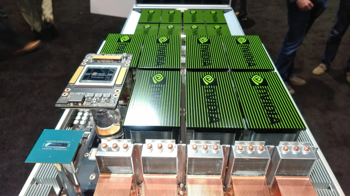
The GPU clusters driving today's AI revolution have outgrown the cooling systems that served the data center industry for decades. A single NVIDIA GB200 NVL72 rack draws approximately 120 kW under full load. Four of those racks in a row produce nearly half a megawatt of heat in a space that traditional HVAC was never designed to handle. Air cooling, the default for enterprise IT since the mainframe era, hits a hard physical ceiling around 20 to 30 kW per rack. Beyond that threshold, the math stops working: the volume of air required, the fan energy consumed to move it, and the floor space dedicated to containment all become impractical.
This guide covers every major liquid cooling approach available to data center operators and GPU hosting providers today. We examine the physics, the economics, the design trade-offs, and the practical deployment considerations for direct-to-chip cooling, single-phase immersion, and two-phase immersion. Whether you are planning a greenfield AI training facility or retrofitting an existing colocation hall for high-density GPU racks, the engineering decisions covered here will determine your power efficiency, operating costs, and long-term flexibility.
The Density Wall: Why Air Cooling Cannot Keep Up
Air is a poor thermal conductor. Its specific heat capacity is roughly 1 kJ per kilogram per degree Celsius, compared to approximately 4.2 kJ for water. To remove the same amount of heat, air cooling requires roughly four times the mass flow rate. At rack densities below 10 to 15 kW, this is manageable with standard CRAC and CRAH units, hot-aisle and cold-aisle containment, and raised-floor plenums. The problems begin when rack power densities climb above 20 kW.
Consider what modern GPU hardware demands:
| GPU Platform | Typical Server Power (8-GPU) | Full Rack Power | Air Cooling Feasible? |
|---|---|---|---|
| NVIDIA A100 SXM | 6.5 kW | 25-30 kW | At the limit |
| NVIDIA H100 SXM | 10-10.5 kW | 40-45 kW | Not practical |
| NVIDIA H200 SXM | 11-12 kW | 45-50 kW | No |
| NVIDIA B200 / GB200 | 14-15 kW | 60-70 kW (per tray) | No |
| NVIDIA GB200 NVL72 (full rack) | N/A (integrated rack) | 120-132 kW | Requires liquid cooling by design |
At 40 kW per rack, an air-cooled data hall must move approximately 10,000 cubic feet per minute of air through each rack to maintain junction temperatures within spec. The fan power alone can consume 15 to 20 percent of the IT load. At 100+ kW, the airflow velocities required would create acoustic problems, the ductwork would dominate the floor plan, and the supply temperature differential would need to be so large that humidity control becomes unreliable.
The industry response has been liquid cooling, and Goldman Sachs estimates that 76 percent of AI servers deployed by the end of 2026 will be liquid-cooled. The shift is not a preference. It is a physical requirement.
Types of Liquid Cooling for GPU Data Centers
Liquid cooling for data centers falls into three broad categories, each with different thermal capacity, complexity, and cost profiles. Understanding the differences is critical because each approach suits different deployment scenarios, and choosing the wrong one can lock you into infrastructure that does not match your workload evolution.
Direct-to-Chip (Cold Plate) Cooling
Direct-to-chip cooling, also called cold plate cooling, is the most widely deployed form of liquid cooling in GPU data centers today. A cold plate, typically machined copper or aluminum with internal microchannels, is mounted directly on top of the GPU die or CPU package. Warm water or a water-glycol mixture circulates through the cold plate, absorbing heat by conduction, and carries it to a coolant distribution unit (CDU) where the heat is transferred to the facility water loop or rejected to a dry cooler.
Key characteristics of direct-to-chip cooling:
- Thermal capacity: Handles 60 to 130+ kW per rack, sufficient for current-generation GPU platforms including H100, H200, and GB200 NVL72 systems.
- Coolant temperatures: Operates with supply water temperatures of 30 to 45 degrees Celsius, which is warm enough to enable free cooling via dry coolers in most climates for much of the year. This eliminates the need for mechanical chillers in many deployments.
- Server compatibility: Works with standard rack-mount servers. NVIDIA DGX systems, Supermicro GPU servers, and Dell PowerEdge XE series all offer direct-to-chip cooling options with quick-disconnect fittings at the rear of the chassis.
- Hybrid airflow requirement: Cold plates cool the GPU and CPU, but other components (memory, VRMs, NVLink bridges, PCIe switches, storage drives) still require supplemental air cooling. A typical direct-to-chip rack dissipates 70 to 85 percent of its heat to liquid, with the remaining 15 to 30 percent handled by reduced-capacity fans.
- Infrastructure: Requires in-rack manifolds, flexible hoses with non-drip quick-disconnect fittings, a CDU per row or cluster, and facility water supply and return piping.
Deployment note: The NVIDIA GB200 NVL72 rack ships with an integrated liquid cooling manifold. Approximately 115 kW of its 120 kW load is liquid-cooled, with only 17 kW of supplemental air cooling for switches and ancillary components. This is the reference architecture that Vertiv, CoolIT, and other cooling vendors have co-developed with NVIDIA.
Single-Phase Immersion Cooling
Single-phase immersion cooling submerges servers entirely in a bath of thermally conductive but electrically non-conductive dielectric fluid. The fluid absorbs heat from all components simultaneously, including those that cold plates cannot reach, such as memory DIMMs, VRMs, and storage drives. The heated fluid is circulated through a heat exchanger where it transfers heat to a secondary water loop.
Key characteristics:
- Thermal capacity: Supports 100 to 250+ kW per tank, depending on tank size and fluid circulation rate. This is the highest-density option for standard server form factors.
- Complete heat capture: Unlike direct-to-chip, immersion cooling removes 100 percent of the heat to liquid. There is no residual air cooling requirement, which means no fans, no hot-aisle containment, and no raised-floor plenum.
- Fluid types: Common single-phase fluids include synthetic hydrocarbons, mineral-oil derivatives, and engineered synthetic fluids. Costs range from approximately $10 to $50 per liter for standard synthetics up to $200 or more per liter for high-performance engineered fluorocarbons. Fluid lifespan is typically 5 to 8 years before reconditioning or replacement.
- Server modifications: Servers require removal of all fans, heatsinks, and thermal interface materials. Some components need conformal coating. Not all server vendors validate their hardware for immersion, so warranty coverage varies.
- Maintenance considerations: Accessing hardware for repair or replacement requires draining or partially draining the tank, and components come out coated in dielectric fluid. Operators need drip trays, fluid recovery procedures, and staff trained in immersion-specific handling.
Immersion cooling has been widely deployed in Bitcoin mining operations, where the economics of hash-rate density per square foot justify the infrastructure. For GPU and AI workloads, immersion is gaining traction in purpose-built facilities where the compute density demands and the elimination of air-side infrastructure produce measurable total cost of ownership advantages.
Two-Phase Immersion Cooling
Two-phase immersion cooling uses a low-boiling-point dielectric fluid that evaporates on contact with hot components, absorbing large amounts of energy through the phase change from liquid to vapor. The vapor rises to a condenser coil at the top of the sealed tank, returns to liquid, and falls back into the bath. This passive cycle requires no pumps for the primary cooling loop, which eliminates a significant energy consumer and mechanical failure point.
Key characteristics:
- Thermal capacity: The highest of any cooling method. The latent heat of vaporization of two-phase fluids (such as 3M Novec or similar fluoroketones) absorbs far more energy per unit mass than single-phase convective heat transfer. Individual tanks can support 250 kW or more.
- PUE potential: Two-phase systems have demonstrated PUE values of 1.02 to 1.03 in controlled deployments, which is as close to theoretical minimum as any production cooling system has achieved.
- Fluid cost: Engineered two-phase fluids are significantly more expensive than single-phase alternatives, with costs of $200 to $300+ per liter. Fluid loss from evaporation (even in sealed systems) and the need for high-purity fluid add to ongoing operating costs.
- Maturity: Two-phase immersion remains less commercially mature than direct-to-chip or single-phase immersion. The number of validated server platforms is smaller, maintenance procedures are more specialized, and the supply chain for two-phase fluids is more concentrated.
- Use cases: Best suited for the absolute highest density deployments where the PUE improvement and space reduction justify the fluid cost premium, or for environments where ambient temperatures make other approaches impractical.
Cooling Approach Comparison
| Parameter | Air Cooling | Direct-to-Chip | Single-Phase Immersion | Two-Phase Immersion |
|---|---|---|---|---|
| Max rack density | 20-30 kW | 60-130+ kW | 100-250+ kW | 250+ kW |
| Typical PUE | 1.4-1.8 | 1.10-1.25 | 1.03-1.10 | 1.02-1.05 |
| Heat to liquid | 0% | 70-85% | 100% | 100% |
| Server modification | None | Cold plate mount | Fan/heatsink removal | Fan/heatsink removal |
| Supplemental air needed | N/A (all air) | Yes (15-30%) | No | No |
| CapEx premium over air | Baseline | +25-35% | +25-40% | +40-60% |
| OpEx cooling savings | Baseline | 30-50% | 40-60% | 50-65% |
| Free cooling potential | Limited | High (warm water) | High | Very high |
PUE and Energy Efficiency Gains
Power Usage Effectiveness measures total facility power divided by IT equipment power. A PUE of 1.0 would mean every watt entering the facility goes to compute. In practice, the gap between 1.0 and the actual PUE represents cooling, lighting, power distribution losses, and other overhead.
The Uptime Institute's 2025 Global Data Center Survey reported a weighted average PUE of 1.54 across the industry, a number that has barely moved from the 1.55 to 1.59 band observed since 2020. Air-cooled facilities with aggressive optimization (variable-speed fans, hot-aisle containment, economizer hours) can reach 1.3 to 1.4 in favorable climates. In hot-arid regions like the UAE or Middle East, air-cooled PUE commonly runs 1.5 to 1.8 because of the limited economizer hours and the chiller energy required to maintain supply air temperatures.
Liquid cooling changes this equation fundamentally:
- Direct-to-chip systems operating with warm-water supply temperatures (35 to 45 degrees Celsius) can reject heat to ambient via dry coolers without mechanical chillers for most of the year in temperate climates. Measured PUE values of 1.10 to 1.25 are typical in production deployments. In climates requiring supplemental chilling, PUE of 1.20 to 1.35 is achievable.
- Single-phase immersion eliminates fan energy entirely (fans represent 5 to 10 percent of IT power in air-cooled servers) and captures 100 percent of heat to liquid, enabling PUE of 1.03 to 1.10.
- Two-phase immersion adds the efficiency of passive phase-change circulation, with demonstrated PUE values of 1.02 to 1.03.
What the numbers mean in practice: For a 10 MW IT load, reducing PUE from 1.55 (air-cooled) to 1.12 (direct-to-chip liquid) saves approximately 4.3 MW of cooling overhead. At $0.06 per kWh, that is approximately $2.26 million per year in electricity savings on cooling alone. Over a 10-year facility life, the savings exceed $22 million before accounting for reduced mechanical maintenance and extended hardware lifespan.
Water Usage Considerations
A common concern with liquid cooling is water consumption. Counter-intuitively, direct-to-chip liquid cooling can use less water than air cooling. Air-cooled facilities in warm climates frequently rely on evaporative cooling towers, which consume 1.8 to 3.0 liters of water per kWh of heat rejected. Direct-to-chip systems using dry coolers (air-to-liquid heat exchangers with no evaporation) consume zero water for heat rejection. Even when supplemental evaporative assistance is needed during peak summer conditions, the Water Usage Effectiveness (WUE) of liquid-cooled facilities is typically 50 to 70 percent lower than comparable air-cooled facilities with cooling towers.
Design Considerations: Engineering a Liquid-Cooled Facility
Plumbing and Fluid Distribution
The plumbing infrastructure for liquid cooling is the most significant departure from traditional data center design. A typical direct-to-chip deployment requires:
- Facility water loop: Large-diameter supply and return piping from the heat rejection plant (dry coolers, cooling towers, or district cooling connection) to the data hall. Pipe sizing must account for the full facility load plus margin for future expansion.
- Coolant distribution units (CDUs): One CDU per row or per cluster of racks, typically occupying 2 to 4 rack footprints on the data hall floor. The CDU contains a heat exchanger that separates the facility water loop from the IT-side coolant loop, pumps, filtration, and monitoring instrumentation. CDU capacity ranges from 100 kW to 1 MW per unit depending on the manufacturer and model.
- In-rack manifolds: Each rack has supply and return manifold headers with quick-disconnect fittings for individual server connections. Non-drip quick-disconnect couplings are standard to prevent coolant spills during server hot-swap operations.
- Leak detection: Rope-style leak detection sensors under racks and along pipe runs, with integration into the building management system (BMS) for automated alerts and, in some designs, automated isolation valve closure.
Fluid Selection
For direct-to-chip systems, the coolant is typically deionized water or a water-propylene glycol mixture (25 to 40 percent glycol depending on freeze protection requirements). This is inexpensive, non-toxic, and has excellent thermal properties. Corrosion inhibitors and biocides are added and monitored regularly.
For immersion systems, the fluid selection is more consequential. Single-phase dielectric fluids range from $10 per liter for basic synthetic hydrocarbons to $50 or more per liter for engineered synthetics with optimized thermal conductivity and material compatibility. Two-phase fluids like fluoroketones cost $200 to $300+ per liter but offer superior thermal performance. The fluid choice affects initial fill cost (a single immersion tank may require 500 to 1,500 liters), ongoing top-up costs from evaporation losses, and component compatibility requirements.
Containment and Safety
Any liquid in a data center introduces the risk of leaks reaching IT equipment. Design mitigations include:
- Secondary containment: Drip trays under racks, sealed cable entry points, and containment dams around CDU footprints. For immersion tanks, secondary containment basins sized to hold the full fluid volume of the largest tank.
- Separation of water and IT coolant loops: CDUs use heat exchangers to keep facility water (which may contain treatment chemicals) physically separated from the IT-side coolant. A leak in the CDU heat exchanger does not introduce contaminated water into the server loop.
- Isolation valves: Automated ball valves on supply and return manifolds allow a leaking rack or CDU to be isolated without shutting down adjacent equipment.
- Material compatibility: All gaskets, hoses, and fittings must be rated for the specific coolant in use. Dielectric fluids in immersion systems can degrade certain plastics and elastomers, requiring validation of every component in the fluid path.
Maintenance and Operations
Liquid-cooled facilities require different operational skills than air-cooled environments. Maintenance procedures include:
- Coolant quality monitoring: Regular testing of pH, conductivity, particulate count, and inhibitor concentration for water-based coolants. For dielectric fluids, testing for breakdown products and contamination.
- Filter replacement: CDU-side filters require periodic replacement to prevent particulate buildup that can restrict flow and reduce heat transfer efficiency.
- Pump maintenance: CDU pumps are the primary mechanical component requiring maintenance. Redundant pump configurations (N+1) allow maintenance without cooling interruption.
- Server hot-swap procedures: Disconnecting and reconnecting coolant hoses during server replacement. Non-drip quick-disconnect fittings minimize fluid loss, but technicians must follow specific procedures to avoid air introduction into the coolant loop.
- Immersion-specific: Draining, cleaning, and refilling tanks for maintenance. Managing fluid-coated hardware during repairs. Tracking fluid levels and top-up requirements.
Economics: CapEx Versus OpEx
The capital cost of liquid cooling infrastructure exceeds air cooling by 25 to 40 percent, depending on the approach. Direct-to-chip systems add approximately $2,500 to $4,500 per kW in cooling infrastructure costs compared to air cooling. Single-phase immersion tanks cost $5,000 to $15,000 per rack equivalent including fluid fill and monitoring. Two-phase turnkey systems range from $22,000 to $38,000 per rack.
However, the CapEx comparison is incomplete without considering two factors that shift the economics decisively in favor of liquid cooling at high densities:
Floor Space Density
A liquid-cooled rack at 120 kW replaces four to six air-cooled racks at 20 to 30 kW each, plus their associated containment, CRAC/CRAH floor units, and plenum space. In expensive real estate markets or capacity-constrained facilities, the floor space savings alone can offset the cooling infrastructure premium. A 1 MW deployment that requires 10 liquid-cooled racks instead of 40 air-cooled racks frees approximately 30 rack footprints (including aisle space) for additional compute.
Operating Cost Savings
The OpEx advantages compound over time:
- Cooling energy: 30 to 60 percent reduction depending on approach, as detailed in the PUE section above.
- Fan elimination: Immersion cooling removes server fans entirely, reducing IT power draw by 5 to 10 percent. This also eliminates fan replacement as a maintenance item.
- Hardware lifespan: Lower and more uniform component temperatures reduce thermal cycling stress. Industry data suggests a 15 to 25 percent improvement in mean time between failures for liquid-cooled versus air-cooled servers, though this varies by deployment and is difficult to isolate from other variables.
- Mechanical systems: Eliminating or reducing chillers, air handlers, and humidification systems reduces both energy consumption and mechanical maintenance labor.
At rack densities above 50 kW, the payback period for the liquid cooling CapEx premium is typically 18 to 24 months based on cooling energy savings alone. Including the floor space and hardware longevity benefits, the total cost of ownership over a 5-year period is consistently lower for liquid cooling than for air cooling in high-density GPU deployments.
Retrofitting Versus Greenfield Builds
Retrofit Options for Existing Facilities
Not every operator has the option to build a greenfield liquid-cooled facility. Retrofitting an existing air-cooled data hall is feasible, but the approach depends on the starting infrastructure:
- Rear-door heat exchangers (RDHx): The simplest retrofit. A water-cooled heat exchanger replaces the rear door of existing racks, intercepting exhaust air before it enters the hot aisle. RDHx units can neutralize 30 to 80 kW per rack depending on water flow rate and supply temperature. They require only a water supply loop to the back of the rack row. No server modification is required. This is the fastest path to increased density in an existing facility.
- Direct-to-chip with CDU: Requires installing CDUs on the data hall floor (consuming 2 to 4 rack positions per row), running supply and return piping to each rack position, and deploying servers with factory-installed cold plates. The existing CRAC/CRAH units remain in service to handle the residual air-cooled heat (15 to 30 percent of total).
- Immersion tank deployment: Replacing standard racks with immersion tanks usually requires structural assessment (tanks are significantly heavier than racks when filled with fluid), floor reinforcement, and reconfiguration of power distribution to match tank positions. The air-handling infrastructure can be decommissioned or repurposed for the remaining air-cooled racks in a mixed deployment.
Greenfield Design Advantages
A purpose-built liquid-cooled facility offers substantial advantages over retrofit:
- Piping integration: Water distribution piping can be run overhead or under the slab during construction, eliminating the floor-level obstructions and retrofit pipe routing challenges of adding plumbing to an existing hall.
- Floor loading: Slab design accounts for the weight of filled immersion tanks or high-density racks from the start, avoiding expensive structural reinforcement.
- Elimination of air infrastructure: No raised floor, no CRAC units, no containment curtains, no large air handler rooms. This reduces construction cost for the portions of the mechanical system that liquid cooling replaces, partially offsetting the liquid cooling investment.
- Heat rejection optimization: The heat rejection plant (dry coolers, adiabatic coolers, or district cooling connection) can be sized and located optimally for the liquid cooling load profile rather than constrained by existing equipment positions.
For new AI training facilities targeting 50+ kW per rack, greenfield liquid-cooled design is the clear economic choice. The total construction cost per kW of IT capacity is often equal to or lower than an air-cooled facility of the same capacity because the mechanical savings offset the plumbing additions.
Deployment for AI Training Versus Inference Workloads
AI training and AI inference impose different demands on cooling infrastructure, and the optimal cooling strategy differs between them.
AI Training Clusters
Training workloads are characterized by sustained, near-maximum GPU utilization for hours, days, or weeks at a time. Every GPU in the cluster runs at or near its thermal design power continuously. This produces a consistent, high heat load with minimal variation.
Cooling implications for training:
- Steady-state design: The cooling system must handle peak load continuously, not as a burst condition. Oversizing for peak is less relevant because peak is the normal operating state.
- Density maximization: Training clusters prioritize GPU-to-GPU interconnect bandwidth (InfiniBand or NVLink), which means packing GPUs as close together as possible. This naturally drives toward the highest density per rack, making liquid cooling a requirement for any cluster built on current-generation hardware.
- Uniform temperature: GPU clock speeds and training throughput are affected by thermal throttling. Liquid cooling provides more uniform die temperatures across the cluster than air cooling, reducing variance in per-GPU performance and improving training efficiency. A 5 to 10 degree Celsius reduction in peak junction temperature can maintain boost clocks that would otherwise throttle under air cooling.
- Recommended approach: Direct-to-chip liquid cooling is the standard for training clusters using H100, H200, and GB200 platforms. Immersion cooling is an option for facilities that also serve mining or mixed workloads, or where ambient temperatures make air-side heat rejection impractical year-round.
AI Inference Deployments
Inference workloads are more variable. GPU utilization fluctuates with request volume, often cycling between 20 and 80 percent utilization across the day. Inference servers are often lower-density than training servers (using fewer GPUs per node or PCIe-attached rather than SXM GPUs), and the thermal load varies proportionally with utilization.
Cooling implications for inference:
- Variable load: The cooling system must efficiently handle a wide range of heat loads without the energy waste of running at full capacity when the IT load is low. Variable-speed pumps and fans on CDUs and dry coolers are essential.
- Mixed density: Inference deployments may coexist with storage, networking, and CPU-heavy preprocessing nodes. A flexible cooling approach that handles 10 to 60 kW racks in the same hall is valuable. Direct-to-chip with row-based CDUs accommodates this mix well.
- Scale-out expansion: Inference capacity often scales incrementally as demand grows, rather than deploying a fixed cluster all at once. Modular cooling that can be added per row or per rack is preferable to monolithic immersion tank installations.
- Recommended approach: Direct-to-chip liquid cooling or rear-door heat exchangers for inference-focused facilities. The density demands are lower than training, the utilization is more variable, and the need for incremental scaling favors approaches that do not require full immersion infrastructure.
Equipment Considerations for Operators
For operators deploying liquid-cooled infrastructure at smaller scale or in containerized environments, the equipment market has matured significantly. Immersion cooling containers and modular tank systems are available at a range of price points and capacities:
- Modular immersion tanks: Single-rack immersion tanks (such as the SLIC tank) are available at the $5,000 price point on the used market, making immersion accessible for pilot deployments and smaller operators without six-figure initial investments.
- Purpose-built immersion pods: Systems like the DCX Bitpod ($2,900) provide single-unit immersion enclosures suitable for individual ASIC miners or small GPU systems, enabling operators to test immersion cooling with minimal capital commitment.
- Scaled immersion systems: For production-scale deployments, turnkey 240 kW immersion systems (such as the DCX platform) are available at approximately $45,000, providing a complete cooling solution for a row of high-density equipment.
- Compact immersion enclosures: For operators transitioning mining operations to liquid cooling, compact enclosures like the SuperCube (approximately $2,000 each, housing 5 to 7 S19-type miners) offer a stepping-stone from air to immersion without full facility conversion.
These equipment options make liquid cooling accessible not only to hyperscale operators but also to GPU hosting providers and colocation operators building high-density capacity incrementally. Rax provides access to these systems through its equipment and hosting programs, with configurations available for both mining and AI/HPC workloads.
Making the Decision: A Framework for Operators
The choice between cooling approaches is ultimately driven by four variables: rack density, facility type (greenfield versus retrofit), workload profile, and budget timeline.
- Below 30 kW per rack: Air cooling remains viable. Invest in hot-aisle containment and high-efficiency CRAC/CRAH units. Plan for liquid cooling as your next GPU generation will likely push past this threshold.
- 30 to 60 kW per rack: Rear-door heat exchangers or direct-to-chip cooling. Both work as retrofits. Direct-to-chip is preferable if your server vendor offers factory-installed cold plates.
- 60 to 130 kW per rack: Direct-to-chip liquid cooling is the standard. This is where H100/H200 clusters and GB200 NVL72 systems operate. Plan for CDU floor space and facility water infrastructure.
- 130+ kW per rack or extreme ambient environments: Single-phase or two-phase immersion. The CapEx premium is justified by the density gains and elimination of all air-side infrastructure. Best suited for greenfield builds or containerized deployments where the facility is designed around the cooling system from the start.
Regardless of the approach chosen, the trajectory is clear. Every major GPU platform on the current and announced roadmaps assumes liquid cooling at full density. The question for operators is not whether to adopt liquid cooling, but when and which approach best fits their deployment timeline and workload mix.
Frequently Asked Questions
How much power can liquid-cooled GPU racks handle compared to air-cooled racks?
Air-cooled racks typically max out at 20 to 30 kW per rack, with aggressive hot-aisle containment pushing some deployments to 40 kW. Direct-to-chip liquid cooling handles 60 to 130 kW per rack. Single-phase immersion cooling supports 100 to 250 kW or more per tank. The NVIDIA GB200 NVL72, which draws approximately 120 kW per rack, requires liquid cooling by design and cannot operate with air cooling alone.
What PUE can a liquid-cooled GPU data center achieve?
Direct-to-chip liquid cooling facilities typically achieve a PUE of 1.10 to 1.25 at full load, compared to the industry average of 1.55 to 1.58 for air-cooled facilities. Two-phase immersion cooling has demonstrated PUE values as low as 1.02 to 1.03 in controlled deployments. These improvements translate to 25 to 40 percent lower cooling energy costs compared to air cooling.
Is liquid cooling required for NVIDIA H100 and B200 GPU servers?
It depends on rack density. A single H100 SXM server draws approximately 10 kW, and a rack of four draws 40 to 45 kW, which is at or beyond the practical limit for air cooling. B200-based systems and the GB200 NVL72 platform, drawing 120 kW or more per rack, require liquid cooling by design. Air-cooled variants exist for lower-density H100 PCIe deployments, but any deployment targeting full rack density with current-generation GPUs will need liquid cooling.
How much does liquid cooling cost compared to air cooling for a GPU data center?
Liquid cooling infrastructure carries a 25 to 40 percent capital cost premium over air cooling, with direct-to-chip systems adding approximately $2,500 to $4,500 per kW. However, the operating cost savings of 40 to 60 percent on cooling energy typically produce a payback period of 18 to 24 months at rack densities above 50 kW. When accounting for the reduced floor space required per kW of IT load, total cost of ownership is often lower for liquid cooling at high densities.
Can I retrofit an existing air-cooled data center with liquid cooling?
Yes, but with constraints. Rear-door heat exchangers are the simplest retrofit, requiring only a water supply loop to the back of existing racks. Direct-to-chip cooling requires in-rack manifolds and a coolant distribution unit (CDU) per row or cluster, typically consuming 2 to 4 rack footprints for the CDU. Full immersion cooling usually requires a floor area redesign because immersion tanks replace standard rack footprints. The key constraint is water supply infrastructure, which many older facilities were not designed to deliver at the volumes liquid cooling demands.
Design Your Liquid-Cooled GPU Infrastructure
Rax Data & Energy provides high-density GPU colocation with direct liquid cooling and immersion cooling infrastructure, supporting rack densities of 130+ kW across facilities in North America, the Middle East, and beyond. From pilot racks to multi-megawatt AI training clusters, our team helps you select, deploy, and operate the right cooling solution for your workload.
Contact Us AI Compute Solutions