Flywheel Energy Storage and Kinetic UPS Systems for Data Centers
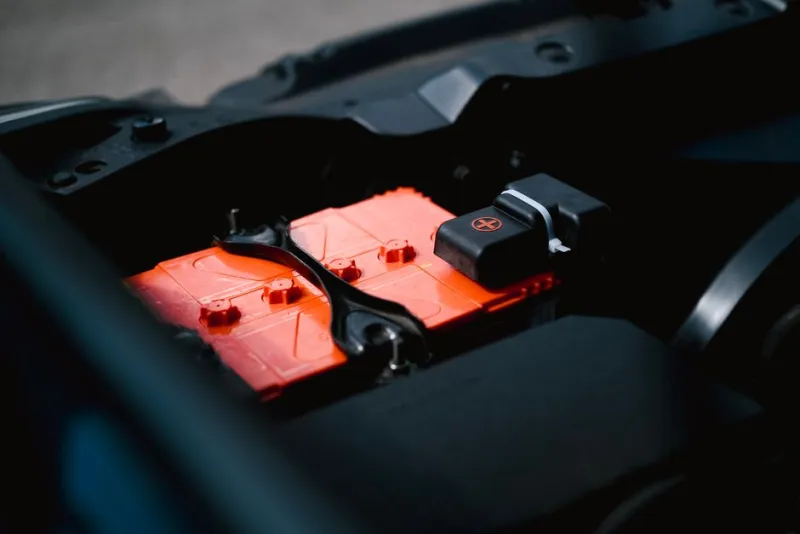
Every data center requires a mechanism to bridge the gap between utility power failure and backup generator startup. For decades, electrochemical batteries -- first valve-regulated lead-acid (VRLA), then increasingly lithium-ion -- have dominated this role. But batteries come with significant operational burdens: they degrade with every charge-discharge cycle, they are sensitive to temperature (particularly in hot-climate data centers), they contain hazardous materials requiring specialized disposal, and they need replacement every 5-10 years at substantial cost.
Flywheel energy storage systems (FESS) offer a fundamentally different approach. Instead of storing energy in chemical reactions, flywheels store energy as rotational kinetic energy in a massive spinning rotor. The physics are straightforward: spin a heavy wheel fast, and it stores energy. When you need that energy back, let the wheel slow down and harvest the rotational energy as electricity. This mechanical approach to energy storage avoids the degradation, temperature sensitivity, and hazardous material challenges of batteries.
Physics of Flywheel Energy Storage
The kinetic energy stored in a rotating flywheel is determined by the equation E = 1/2 * I * omega^2, where I is the moment of inertia (determined by rotor mass and geometry) and omega is the angular velocity. Two design approaches maximize stored energy:
High-Mass, Low-Speed Flywheels
Traditional flywheel designs use large steel rotors (1,000-5,000 kg) spinning at moderate speeds (3,600-7,700 RPM). The energy density comes from the mass of the rotor. These designs are mechanically simpler, use conventional bearings, and have decades of field history. Manufacturers include Hitec Power Protection (now part of Rolls-Royce) and Piller. The trade-off is physical size: a steel flywheel system rated for 1 MW of ride-through power requires a footprint comparable to a shipping container.
Low-Mass, High-Speed Flywheels
Modern flywheel designs use lighter composite rotors spinning at very high speeds (20,000-36,000+ RPM) in vacuum-sealed enclosures with magnetic bearings. The quadratic relationship between energy and speed means that doubling the rotational speed quadruples the stored energy. A 100 kg composite rotor spinning at 36,000 RPM stores more energy than a 1,000 kg steel rotor spinning at 7,700 RPM. These systems are far more compact but require more sophisticated engineering: magnetic bearings to eliminate friction (mechanical bearings cannot handle the speeds), vacuum enclosures to eliminate air resistance (which would otherwise dissipate the stored energy as heat), and advanced containment structures in case of rotor failure. Manufacturers include Beacon Power, Active Power (now Piller), and Calnetix/Vycon.
Energy and Power Capacity
A single flywheel module typically stores 1-10 kWh of usable energy and can deliver 100-500 kW of power. For data center applications, multiple flywheel modules are paralleled to achieve the required power and energy capacity. A 2 MW data center power system might use four 500 kW flywheel modules, providing 15-20 seconds of ride-through at full load.
Importantly, flywheels are power-dense but energy-sparse: they can deliver very high power for a short duration, but they cannot sustain output for the minutes that batteries can. This is by design -- the flywheel only needs to bridge the 8-15 seconds between utility failure and generator start and load acceptance. If the generator fails to start within the flywheel's ride-through time, the load drops. This makes generator reliability and start time the critical pairing consideration for flywheel installations.
Rotary UPS (DRUPS) Architecture
The most comprehensive flywheel implementation for data centers is the Diesel Rotary UPS (DRUPS), which integrates a flywheel, motor/generator, and diesel engine into a single system. A DRUPS replaces three separate systems in a traditional architecture: the static UPS, the battery bank, and the diesel generator.
How DRUPS Works
Under normal operation, utility power drives the motor, which spins the flywheel and generator at synchronous speed (typically 1,500 RPM for 50 Hz systems). The generator output feeds the critical IT load. The flywheel accumulates kinetic energy while the system is running. When utility power fails:
- The flywheel immediately begins decelerating, converting kinetic energy to electrical energy through the generator. This happens instantaneously -- there is zero transfer time because the generator is already spinning and producing power.
- Simultaneously, the diesel engine receives a start signal. Modern DRUPS diesel engines reach rated speed within 5-8 seconds.
- A clutch mechanism engages the diesel engine to the generator shaft. The diesel engine's mechanical power replaces the flywheel's kinetic energy as the primary energy source.
- The generator continues to produce clean, regulated power to the IT load throughout this transition. The load never experiences an interruption because the generator never stopped spinning.
The elegance of DRUPS is the continuous mechanical coupling: the load is always powered by a spinning generator, and the energy source driving that generator transitions seamlessly from utility motor to flywheel kinetic energy to diesel engine mechanical power.
Power Conditioning Through Inertia
One significant but often overlooked advantage of rotary UPS systems is inherent power conditioning. The massive rotating assembly (flywheel, motor, generator) acts as a mechanical low-pass filter. Voltage transients, harmonics, frequency variations, and other power quality disturbances on the utility input are absorbed by the mechanical inertia of the system before reaching the generator output. The generator output is a clean sine wave at precisely controlled voltage and frequency, regardless of input power quality.
This contrasts with static UPS systems, which use electronic rectifiers, inverters, and digital signal processing to condition power. While modern static UPS systems produce excellent output quality, they can be affected by non-linear loads (like the switched-mode power supplies in GPU servers) that generate harmonics feeding back into the UPS input. Rotary systems are inherently immune to these harmonic feedback issues because the mechanical coupling provides galvanic isolation between input and output.
Flywheel vs Battery: Detailed Comparison
| Characteristic | Flywheel/DRUPS | Static UPS + VRLA Battery | Static UPS + Li-ion Battery |
|---|---|---|---|
| Ride-through time | 10-30 seconds | 5-15 minutes | 5-15 minutes |
| Service life | 20-25 years (rotor) | 5-7 years (battery) | 8-12 years (battery) |
| Temperature sensitivity | Minimal (40C+ capable) | High (requires 20-25C) | Moderate (tolerates 30-35C) |
| Cycle degradation | None (unlimited cycles) | Significant (500-1,500 cycles) | Low (3,000-5,000 cycles) |
| Hazardous materials | None (steel, copper, magnets) | Lead, sulfuric acid | Lithium, cobalt, electrolytes |
| Floor loading | High (massive rotor) | High (heavy battery racks) | Moderate (lighter than VRLA) |
| Maintenance frequency | Annual (bearing inspection) | Quarterly (capacity testing) | Semi-annual (BMS verification) |
| Capex (per MW) | Higher (integrated system) | Lower (commodity components) | Moderate (premium cells) |
| 20-year TCO (per MW) | Lower (no battery replacements) | Higher (3-4 battery replacements) | Moderate (1-2 replacements) |
Total Cost of Ownership Analysis
The TCO comparison between flywheel and battery-based UPS systems depends heavily on the time horizon and operational assumptions.
Capital Cost
A DRUPS system typically costs 30-50% more per MW than a static UPS with VRLA batteries at initial installation. However, the DRUPS replaces both the UPS and the generator, so the comparison must include the cost of separate diesel generators in the static UPS architecture. When generators are included, the capital cost difference narrows to 10-20%.
Battery Replacement Costs
Over a 20-year facility life, VRLA batteries require 3-4 complete replacements at approximately 40-50% of the original battery bank cost each time. Lithium-ion batteries require 1-2 replacements. Flywheel rotors require zero replacements -- the primary rotor components (steel, composite, magnets) do not degrade with use. Bearings and seals may need replacement once in a 20-year period at modest cost.
Cooling Cost Savings
VRLA batteries require dedicated climate-controlled rooms maintained at 20-25 degrees C to prevent accelerated degradation. In Gulf climates where outside air temperature regularly exceeds 45 degrees C, battery room cooling represents a significant energy cost. Flywheel systems tolerate ambient temperatures up to 40 degrees C or higher without performance degradation, eliminating the dedicated cooling requirement. The annual cooling energy savings can reach $15,000-$30,000 per MW of UPS capacity in hot-climate installations.
Space Savings
A DRUPS system (combining UPS and generator) occupies less total floor space than separate static UPS, battery room, and generator installations. For data centers where floor space has a direct revenue opportunity cost (space not used for power infrastructure can house revenue-generating IT equipment), this space efficiency has tangible financial value.
Deployment Considerations for AI Data Centers
The rise of high-density AI compute infrastructure creates specific considerations for flywheel UPS selection:
Dynamic Load Profiles
GPU training workloads exhibit highly dynamic power profiles. A server with eight H100 GPUs might draw 2 kW at idle but 10.2 kW during peak training. When a distributed training job starts across hundreds of GPUs simultaneously, the data center power demand can ramp by several MW within seconds. Flywheel systems handle these transient loads well because the rotating mass provides inherent load following: the generator output tracks load changes through the mechanical coupling without the electronic response time required by static UPS inverters.
Power Density Matching
AI data centers increasingly operate at 40-80 kW per rack, compared to 6-10 kW per rack for traditional enterprise workloads. This concentration of power makes the high power density of DRUPS systems advantageous: a single 3 MW DRUPS unit can protect 150-300 racks of traditional IT or 38-75 racks of high-density GPU equipment, occupying less space than equivalent battery-based protection.
Generator Start Reliability
Because flywheel ride-through time is limited to 10-30 seconds, the reliability and start speed of backup generators is critical. DRUPS systems with integrated diesel engines address this by having the engine physically coupled to the system -- there is no separate generator that needs to start, synchronize, and close a transfer switch. For standalone flywheel UPS systems paired with separate generators, the generator start sequence must be tested and validated to complete within the flywheel's ride-through window, with margin for safety.
Seismic Considerations
High-speed flywheel rotors contain enormous kinetic energy. A 250 kW flywheel spinning at 36,000 RPM stores approximately 3.5 kWh of energy -- equivalent to the kinetic energy of a car traveling at highway speed. Flywheel enclosures are engineered to contain the rotor in the event of bearing failure or rotor fracture, but seismic events can impose lateral forces on the containment structure. In seismically active regions, flywheel installations require seismic analysis and anchoring to building structure. The UAE's low seismicity makes it a favorable geography for flywheel deployments.
Hybrid Architectures: Flywheel Plus Battery
Some data center designs use both flywheel and battery storage in a complementary architecture:
- Flywheel for short interruptions: The flywheel handles the most common power events -- momentary utility dips, brief outages under 15 seconds, voltage sags -- without discharging batteries. Since these events account for 90%+ of utility power disturbances, the battery is rarely discharged, dramatically extending its cycle life.
- Battery for extended outages: When the generator fails to start within the flywheel's ride-through window (a rare but consequential scenario), the battery provides additional minutes of runtime for orderly shutdown or generator troubleshooting.
- TCO optimization: The battery can be sized smaller (only for extended outage coverage, not for the frequent short events that the flywheel handles), reducing battery capital cost and replacement frequency. The flywheel handles the duty cycle that would otherwise degrade the battery fastest.
This hybrid approach is gaining traction in facilities that want the reliability advantages of flywheel technology without accepting the operational risk of flywheel-only architectures (where generator failure within 30 seconds means load loss).
Environmental and Sustainability Advantages
Flywheel systems align with sustainability objectives in several ways:
- No hazardous waste: VRLA batteries contain lead and sulfuric acid; lithium-ion batteries contain lithium, cobalt, and flammable electrolytes. End-of-life disposal requires specialized handling. Flywheel components (steel, copper, rare earth magnets) are fully recyclable through standard metal recycling processes.
- No manufacturing emissions: Battery manufacturing (particularly lithium-ion) involves significant energy-intensive processes and supply chain emissions. Flywheel manufacturing is primarily mechanical fabrication with lower embedded carbon.
- Higher efficiency: DRUPS systems operating in line-interactive mode achieve 96-98% efficiency, comparable to the best static UPS systems. The absence of double conversion (AC-DC-AC) in DRUPS architectures eliminates the conversion losses inherent in static UPS double-conversion designs.
- Longer service life: A 20-year flywheel replaces 3-4 sets of batteries, avoiding the manufacturing emissions and transportation energy of multiple battery replacements.
Installation and Operational Requirements
Structural Requirements
Flywheel systems, particularly low-speed steel-rotor designs, are heavy. A 1 MW DRUPS system can weigh 15,000-25,000 kg. Floor loading analysis and potentially reinforced foundations are required. High-speed composite flywheel modules are lighter (500-2,000 kg per module) but still require secure mounting to prevent movement during a rotor containment event. Vibration isolation mounts are required to prevent flywheel vibration from transmitting to the building structure and sensitive IT equipment.
Acoustic Considerations
Rotating machinery produces noise. Low-speed DRUPS systems generate 75-85 dB at 1 meter, comparable to a diesel generator. High-speed flywheel modules in vacuum enclosures are quieter (60-70 dB) because the vacuum eliminates air drag noise. Acoustic enclosures are typically required for indoor installations adjacent to occupied spaces. For outdoor or purpose-built mechanical room installations, noise is less of a concern.
Maintenance Model
Flywheel maintenance is simpler than battery maintenance but requires different skills. Annual inspections include bearing condition monitoring (vibration analysis, temperature trending), vacuum level verification (for high-speed systems), magnetic bearing controller diagnostics, and diesel engine maintenance (for DRUPS). Unlike batteries, flywheels do not require quarterly capacity tests, cell-level voltage monitoring, or thermal management system verification. The maintenance workforce needs mechanical and rotating machinery skills rather than electrochemical expertise.
Market Landscape and Major Vendors
- Rolls-Royce Power Systems (formerly Hitec): Leading DRUPS manufacturer with MW-class systems deployed in hundreds of data centers globally. Their No-Break KS series integrates flywheel, motor/generator, and diesel engine in a single unit.
- Piller (part of Langley Holdings): Produces both standalone rotary UPS and DRUPS systems. Their UNIBLOCK series is widely deployed in European data centers.
- Beacon Power: Specializes in high-speed composite flywheel modules for grid-scale energy storage. Their 25 kWh/100 kW modules are used in utility frequency regulation and data center UPS applications.
- Vycon (Calnetix Technologies): Produces compact high-speed flywheel modules designed to replace batteries in existing static UPS installations. Their VDC and VDC-XE series provide 300-500 kW per module.
- Euro-Diesel: Belgian manufacturer of DRUPS systems with significant deployment history in European and Middle Eastern data centers.
The GCC Opportunity
The Gulf region's climate and market characteristics make it particularly well-suited for flywheel technology:
- High ambient temperatures: Battery degradation accelerates in heat. Flywheel systems maintain full performance at temperatures that would halve VRLA battery life. This eliminates the cost and energy of battery room air conditioning.
- Rapid market growth: New data center construction in the UAE and GCC allows greenfield facility designs that incorporate DRUPS from the outset, rather than retrofitting into existing battery-based architectures.
- Sustainability mandates: UAE and Saudi Arabia sustainability frameworks favor technologies with lower waste streams and longer service lives. Flywheel systems avoid the lead-acid battery disposal problem that is increasingly regulated in the region.
- Sovereign AI infrastructure: Government-mandated AI compute facilities require the highest reliability tier. DRUPS systems with zero transfer time and inherent power conditioning meet these requirements without the complexity of managing large battery installations.
Design Your Power Infrastructure
Rax designs data center power systems optimized for your workload requirements, reliability targets, and climate conditions. Our engineering team evaluates flywheel, battery, and hybrid architectures to deliver the optimal TCO and reliability for your infrastructure.
Discuss Your Power Requirements