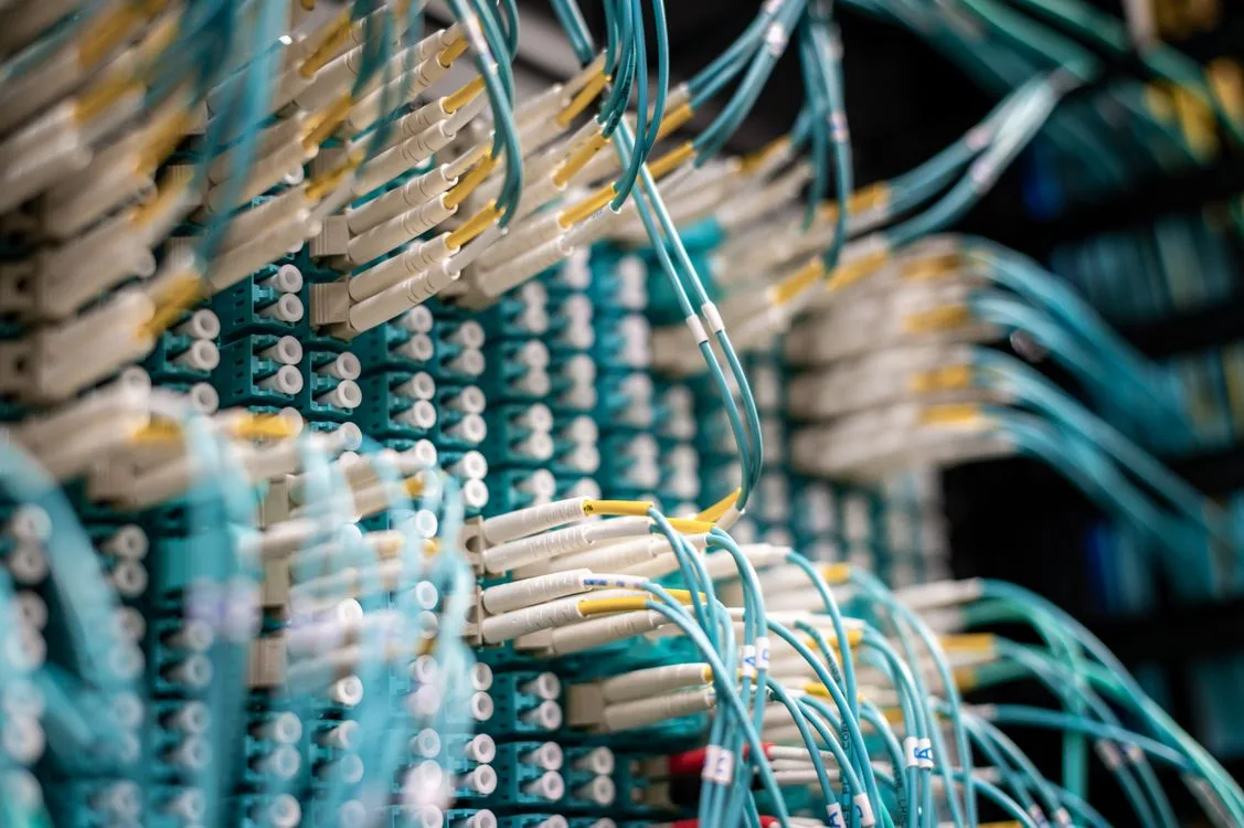
Cable infrastructure represents one of the most overlooked yet critical aspects of data center design. While power distribution and cooling systems receive substantial engineering attention, cable tray and containment systems directly impact installation speed, operational flexibility, maintenance efficiency, and long-term scalability. In high-density AI and GPU data centers where each rack may host 40-80 kW of computing equipment, cable management systems must accommodate hundreds of power and network cables while maintaining thermal management, electrical safety, and future expansion capacity.
This guide examines cable tray design principles, containment system selection, capacity planning methods, and installation best practices for modern high-density data centers hosting AI training clusters, Bitcoin mining operations, and GPU compute infrastructure.
Cable Tray System Types and Applications
Cable tray systems provide structural support for electrical wiring and communication cables. Unlike conduit systems that enclose cables, trays provide open or ventilated pathways that facilitate heat dissipation, enable visual inspection, and simplify future cable additions. High-density data centers typically deploy multiple tray types optimized for different cable categories.
Ladder Cable Tray
Ladder trays consist of two longitudinal side rails connected by transverse rungs, typically spaced 150mm to 300mm apart. This design provides maximum load-bearing capacity for heavy power cables while maintaining excellent ventilation. Ladder trays excel at supporting large copper conductors used for high-amperage circuits feeding GPU racks and power distribution units.
For high-density installations, 900mm wide ladder trays with 300mm rung spacing represent standard practice for main horizontal power distribution above hot aisles. The open rung design allows heat from power cables to dissipate into plenum airflow, preventing hot spots that would derate cable ampacity.
Solid Bottom Cable Tray
Solid bottom trays provide continuous support for small-diameter cables, preventing cables from sagging through rung openings. These trays work well for network cabling, control wiring, and fiber optic runs where cable support must be continuous. However, solid trays trap heat more readily than ventilated designs, requiring larger derating factors for power cable installations.
In practice, solid bottom trays see limited use in high-density data centers except for dedicated fiber optic pathways or control cable systems where electromagnetic shielding benefits outweigh thermal penalties.
Wire Mesh and Basket Tray
Wire mesh trays use welded wire construction to create lightweight, highly ventilated cable support systems. Basket trays with 50mm wire spacing provide excellent visibility for cable tracing, facilitate airflow, and weigh significantly less than ladder or solid trays. These characteristics make basket trays ideal for overhead network cabling and fiber optic distribution.
Data centers commonly deploy basket trays for all data and communication cables, reserving heavier ladder trays exclusively for power distribution. This segregation simplifies troubleshooting and enables specialized installation practices for each cable type.
Tray Sizing and Capacity Planning
Undersized cable trays constrain future expansion and create installation bottlenecks. Oversized trays waste vertical space, increase costs, and complicate support structure design. Proper sizing requires calculating cable quantities, applying fill ratio limits, and reserving capacity for growth.
Cable Fill Calculations
Electrical codes limit cable fill based on tray cross-sectional area and cable types. For single-conductor power cables in ladder trays, fill should not exceed 50 percent of usable tray area to prevent excessive heat concentration. Data center design standards commonly reduce this to 40 percent for initial installations, providing expansion capacity and installation working room.
A 900mm wide by 100mm deep ladder tray has approximately 90,000 square millimeters of usable area. At 40 percent fill, this tray can accommodate 36,000 square millimeters of cable cross-section. A 500 kcmil copper conductor has a cross-sectional area of roughly 400 square millimeters including insulation, allowing approximately 90 such conductors in a single tray section.
Load-Bearing Capacity
Cable weight determines required support spacing and tray gauge. Copper power cables represent the heaviest loading condition. A 500 kcmil copper conductor weighs approximately 3 kg per meter. A 100-meter tray run filled with 90 such conductors would support 27,000 kg of cable—270 kg per meter of tray length.
Ladder trays supporting heavy power cables typically require support at 1.5 to 2.5 meter intervals depending on tray width, material gauge, and cable load. Manufacturer load tables specify maximum support spacing for given loads and tray configurations. Exceeding these limits causes tray sagging, cable stress, and potential support failure.
Future Capacity Reserve
Data centers evolve continuously. Initial deployments rarely represent final configurations. Reserving 40-60 percent tray capacity for future circuits prevents costly tray additions when racks densify or new power distribution requirements emerge. This reserve also accommodates emergency circuit additions without requiring existing cable removal to create working room.
Some facilities deploy oversized trays in primary pathways—900mm trays where 600mm would suffice initially—specifically to enable future growth without infrastructure modifications. The incremental cost of larger trays during initial construction typically represents 10-20 percent of total tray material costs but eliminates expensive retrofit work.
Power and Data Cable Segregation
Separating power and data cables reduces electromagnetic interference, simplifies troubleshooting, meets electrical code requirements, and enables specialized installation practices for each cable type.
Electromagnetic Interference Mitigation
High-current power cables generate electromagnetic fields that can induce noise in adjacent signal cables. While modern twisted-pair and fiber optic cables incorporate shielding and cancellation techniques, physical separation remains the most effective interference prevention method. Maintaining 300-600mm spacing between power trays and data trays eliminates virtually all EMI coupling.
When space constraints prevent adequate separation, metal barriers or center dividers within trays can provide electromagnetic shielding. However, this approach increases installation difficulty, reduces effective tray capacity, and complicates future modifications.
Troubleshooting and Maintenance Efficiency
Segregated tray systems enable technicians to quickly identify cable types and trace circuits without navigating mixed cable bundles. Power circuits can be de-energized for maintenance without disturbing adjacent network infrastructure. New circuit installations proceed faster when installers can access the correct tray system without moving unrelated cables.
Color-coded tray systems—orange for power, yellow for fiber, gray for copper data—further enhance visual identification and reduce installation errors. This coding extends through all tray types, fittings, and support hardware to create consistent visual language throughout the facility.
Routing Strategies for High-Density Installations
Cable tray routing directly impacts installation efficiency, cable bend radius compliance, and future accessibility. Strategic routing decisions made during design prevent operational bottlenecks for years afterward.
Hot Aisle vs. Cold Aisle Routing
Most data centers route primary cable trays above hot aisles, leaving cold aisles clear for cooling infrastructure. This approach places cables in warmer air that requires larger derating factors but simplifies access to rack tops where connections occur. Power cables radiate heat whether in cold or hot aisles, but locating them above hot aisles prevents cable heat from entering cold aisle airflow.
Alternative designs route trays above cold aisles but typically require containment structures that prevent cable heat from affecting intake air temperature. These systems increase installation complexity but can improve cable ampacity by placing conductors in cooler environments.
Vertical Cable Pathways
Transitioning from overhead trays to individual racks requires vertical cable pathways that maintain bend radius requirements while organizing hundreds of cables. Vertical ladder racks mounted to structural columns or dedicated cable chimneys provide organized vertical transitions without consuming valuable rack space.
Cable managers should provide radius compliance for the tightest bend in the system. Large copper power cables may require 300-400mm minimum bend radius, while fiber optic cables demand 10-20 times their diameter—typically 40-60mm. Vertical pathway sizing must accommodate all cable types using the most restrictive bend radius requirements.
Cross-Aisle Cable Crossings
Crossing perpendicular aisles without blocking overhead clearance for equipment movement requires careful tray elevation planning. Main distribution trays typically mount at 3-3.5 meters above finished floor to provide clearance for equipment transport while maintaining accessible mounting heights.
When trays must cross at different elevations, transition fittings should maintain maximum 30-degree slopes to prevent cable slippage and maintain bend radius compliance. Steeper transitions require cable ties at close intervals to prevent gravitational sagging.
Grounding and Bonding Requirements
Cable tray systems function as equipment grounding conductors when properly bonded. All tray sections, fittings, and supports must provide continuous low-impedance paths to ground.
Tray Section Bonding
Tray sections connect through bolted joints that may develop resistance over time due to corrosion, paint, or mechanical stress. Bonding jumpers installed across all joints ensure continuous electrical continuity regardless of joint condition. Copper jumpers sized according to electrical code requirements—typically 6 AWG minimum—bond all tray joints.
Some tray manufacturers provide proprietary bonding systems integrated into splice plates and fittings. These systems can accelerate installation but require verification that bonding remains intact after installation is complete.
Ground Fault Protection
Properly bonded tray systems enable ground fault protection devices to detect and clear faults rapidly by providing low-impedance return paths. Poor bonding increases ground fault impedance, slowing fault clearing times and increasing arc flash hazards.
Bonding verification testing after installation measures resistance between tray sections and main ground bus. Measurements should typically remain below 0.1 ohms for effective ground fault clearing. Higher resistance indicates bonding deficiencies requiring correction.
Installation Best Practices
Proper installation techniques determine whether cable tray systems deliver designed performance and longevity.
Support Structure Adequacy
Cable tray supports must anchor to building structure capable of supporting calculated loads with appropriate safety factors. Mounting to ceiling grid systems or non-structural elements creates collapse risk as cable loads accumulate. Proper support attaches to structural steel, concrete decks, or engineered support systems rated for imposed loads.
Seismic regions require additional bracing and sway limiters that prevent tray movement during earthquakes. UAE seismic design requirements specify lateral bracing at regular intervals and support detailing that maintains tray integrity during ground motion.
Cable Installation Damage Prevention
Cable pulling tension and sidewall pressure during installation can damage cable insulation, reducing service life or causing immediate failures. Using proper cable pulling equipment, maintaining maximum tension limits, and employing cable rollers at all bends prevents installation damage.
For large copper conductors, maximum pulling tension typically limits to 0.008 times the circular mil area in pounds. A 500 kcmil conductor should experience maximum 4,000 pounds tension during installation. Exceeding these limits stretches conductors, damages insulation, or breaks strands.
Fire Stopping at Penetrations
Cable trays penetrating fire-rated walls or floors require approved fire stopping systems that maintain wall fire rating while accommodating cable additions. Intumescent materials expand when heated to seal openings, while mechanical systems use adjustable frames and fire-resistant packing.
Fire stopping systems must allow future cable additions without compromising fire rating. Specifying systems with documented procedures for adding cables after initial installation enables operational flexibility while maintaining code compliance.
Documentation and Labeling
Comprehensive tray documentation enables efficient troubleshooting, simplifies future expansion, and preserves design intent as staff turnover occurs.
Tray Routing Drawings
As-built drawings documenting actual tray routes, elevations, and support locations provide essential references for planning future work. Drawings should include tray sizes, types, elevations at key points, support spacing, and penetration locations. This documentation prevents damaging existing infrastructure during renovations.
Cable Schedule Maintenance
Recording which cables occupy which tray sections prevents overloading and identifies available capacity during expansion planning. Many facilities use color-coded cable markers at tray entry points that reference database records linking cables to circuits and equipment.
Modern building information modeling systems can track cable assignments in three dimensions, generating loading reports by tray section and identifying capacity constraints before installations proceed.
Conclusion
Cable tray and containment infrastructure determines data center operational efficiency, expansion capability, and long-term maintainability. Thoughtful system design that segregates power and data cables, sizes trays for current loads plus growth reserve, maintains proper cable support and bend radius compliance, and implements comprehensive documentation creates infrastructure that supports decades of reliable operation.
For high-density AI and Bitcoin mining facilities where rack power densities reach 40-80 kW and where every rack may require 60-100 cable connections, cable management systems deserve engineering rigor equal to that applied to power distribution and cooling design. The relatively modest investment in properly designed tray systems prevents installation bottlenecks, eliminates future retrofit costs, and ensures that cable infrastructure scales seamlessly as computing density evolves.
Discuss Your Data Center Infrastructure Requirements