What Is Three-Phase Power?
Three-phase power is an electrical power distribution method that uses three alternating current (AC) waveforms, offset by 120 electrical degrees from each other, to deliver power more efficiently and reliably than single-phase systems. It is the universal standard for industrial, commercial, and data center power distribution, and it is the backbone of every mining facility and GPU cluster in the world.
Understanding three-phase power is essential knowledge for anyone involved in mining farm design, data center operations, or any power-intensive infrastructure deployment. It directly affects how you size transformers, select electrical equipment, plan power distribution, calculate operating costs, and ensure safety compliance. This guide provides the foundation you need to make informed decisions about electrical infrastructure for mining and AI hosting operations, whether you are planning a small 1 MW container deployment or a large 50+ MW industrial campus.
How Three-Phase Power Works
The Physics Behind Three Phases
In a three-phase system, three conductors (labeled Phase A, Phase B, and Phase C, or sometimes L1, L2, and L3) each carry an AC voltage waveform. These waveforms are identical in magnitude (voltage level) and frequency (50 or 60 Hz depending on region) but are phase-shifted exactly 120 degrees apart. This means when Phase A is at its positive peak, Phase B is at negative 60% of peak, and Phase C is at positive 60% of peak. The three waveforms are constantly chasing each other around a cycle.
The concept of three-phase power was pioneered by Nikola Tesla in the late 1880s and became the global standard for electrical power generation, transmission, and distribution because of its fundamental advantages over single-phase systems in efficiency, power density, and motor operation. Every large power plant, transmission line, and industrial facility in the world uses three-phase power. Understanding how it works is not optional knowledge for mining and data center operators; it is foundational.
Why Three Phases Are Better Than One
- Constant Power Delivery: The mathematical sum of three sinusoidal waveforms offset by 120 degrees is a constant value, not a pulsating one. Single-phase power drops to zero twice per cycle (120 times per second on a 60 Hz system), creating power pulsation. Three-phase power is smooth and continuous, which is better for motors, power supplies, and electronic equipment.
- More Power with Less Copper: A three-phase system delivers the same total power using approximately 75% of the conductor copper required by three separate single-phase circuits. For large-scale installations where copper runs can be hundreds of feet, this saves significant material cost and reduces installation complexity.
- Motor Efficiency: Three-phase motors are mechanically simpler (no starting capacitors or switches needed), more efficient (2-5% higher efficiency than single-phase), more reliable (fewer moving parts to fail), and more compact than equivalent single-phase motors. This matters for cooling systems that use fans, pumps, and compressors extensively -- see our cooling technology comparison and immersion cooling ROI analysis for how these systems depend on efficient power delivery.
- Balanced Loading: Three-phase systems allow loads to be distributed across three phases, reducing the current flowing through the neutral conductor to near zero when loads are balanced. This reduces wiring costs, minimizes voltage drop, and improves overall system efficiency.
Voltage Levels and Configurations
Common Three-Phase Voltage Configurations
| Configuration | Phase-to-Phase Voltage | Phase-to-Neutral Voltage | Common Application |
|---|---|---|---|
| 120/208V Wye | 208V | 120V | Small commercial buildings, some IT equipment |
| 277/480V Wye | 480V | 277V | Data centers, mining operations (North American standard) |
| 230/400V Wye | 400V | 230V | European data centers and industrial facilities |
| 240V Delta | 240V | N/A (no neutral) | Some industrial applications, older mining deployments |
| Medium Voltage | 4.16kV to 35kV | Varies | Utility distribution to buildings and substations |
| High Voltage | 69kV to 500kV | N/A | Long-distance transmission lines, major substation feeds |
Why 480V Is the Standard for Data Centers and Mining
Most North American data centers and mining operations use 480V three-phase as their primary distribution voltage, and for very good reasons. Higher voltage means proportionally lower current for the same power delivery. Lower current means smaller, lighter, and less expensive cables and busbars; lower resistive losses (I-squared-R losses) in wiring; smaller, less expensive circuit breakers and switchgear; and less heat generated in the distribution infrastructure.
The power savings from using 480V versus 208V distribution can reduce electrical distribution losses by 50% or more. For a mining operation consuming 10 MW continuously, the difference between 480V and 208V distribution can save $50,000-100,000 per year in wasted electricity. Over the lifetime of a facility, this is significant. For a complete breakdown of how electricity costs affect mining profitability, see our electricity cost optimization guide.
Power Calculations for Three-Phase Systems
Essential Formulas
These calculations are critical for planning electrical infrastructure for Mining Farm Design: From 1MW to 100MW - Complete Planning Guide and data center deployments. Every electrician, engineer, and facility manager should have these committed to memory.
Three-Phase Power: P(kW) = V(line-to-line) x I(line) x 1.732 x PF / 1000
Three-Phase Current: I(line) = P(kW) x 1000 / (V(line-to-line) x 1.732 x PF)
Where 1.732 is the square root of 3 (a constant that appears in all three-phase calculations due to the geometry of the three phase vectors), V is the line-to-line voltage, I is the line current per phase, and PF is the power factor (typically 0.95-0.99 for modern IT and mining equipment with active power factor correction).
Practical Calculation Examples
| Scenario | Power | Voltage | Current per Phase | Wire Size (Copper, approx) |
|---|---|---|---|---|
| Single ASIC miner | 3.5 kW | 240V single-phase | ~14.6 A | 14 AWG |
| Mining container (200 units) | 700 kW | 480V three-phase | ~843 A | Multiple parallel 500 MCM runs |
| 1 MW mining building | 1,000 kW | 480V three-phase | ~1,203 A | Busway or multiple parallel feeders |
| GPU server rack (4x DGX) | 45 kW | 480V three-phase | ~54 A | 6 AWG |
| 10 MW facility total | 10,000 kW | 480V three-phase | ~12,028 A | Switchgear + multiple feeders |
Power Distribution Architecture
Typical Distribution Chain for Mining and Data Centers
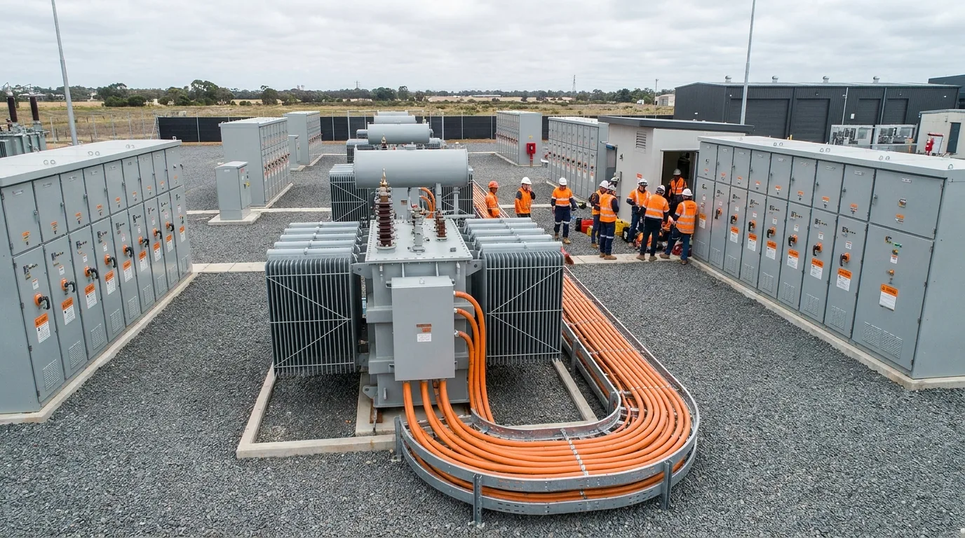
Power flows through multiple stages of transformation and distribution from the utility source to the computing equipment. Each stage must be properly designed and sized, as a bottleneck at any point constrains the entire downstream capacity.
- Utility Interconnection: Medium or high voltage service from the local electric utility, typically 12.47kV, 25kV, 34.5kV, or higher depending on the facility's power demand. Larger facilities (10+ MW) may interconnect at transmission voltage (69kV+) for better rates and reliability.
- Step-Down Transformer: Reduces utility voltage to the facility's primary distribution voltage, usually 480V in North America. Transformers are sized in kVA and must be matched to the expected load plus growth margin. Typical efficiency is 98-99%, meaning 1-2% of all power is lost as heat in the transformer.
- Main Switchgear: The central distribution point with main circuit breakers, protection relays, metering equipment, and bus connections for downstream feeders. This is the control center for the entire facility's power system.
- UPS System (if applicable): Provides battery backup and power conditioning. See Understanding UPS Systems for Data Centers: Types, Sizing, and Best Practices for detailed UPS information. Mining operations often skip UPS to reduce costs, while AI/HPC facilities typically require it.
- Power Distribution Units (PDUs): Step down voltage if needed (e.g., 480V to 208V for servers) and distribute power to individual racks or rows via multiple branch circuits. Learn about the four types of PDUs — basic, metered, switched, and intelligent — each with circuit breakers for branch protection and varying levels of monitoring capability.
- Rack PDU (rack-level strip): The final distribution point, providing individual outlets (typically C13 or C19) for connecting server power supplies. Smart rack PDUs provide per-outlet monitoring for granular power tracking.
- Power Supply Unit (PSU): Inside each server or ASIC miner, the PSU converts facility AC power to the DC voltages (12V, 5V, 3.3V) required by the computing hardware's internal components.
Power Factor: Why It Matters Financially
Power factor is the ratio of real power (kW, the power that actually does useful work and generates heat) to apparent power (kVA, the total power drawn from the supply including reactive components). A power factor of 1.0 means all power drawn is being used productively. A lower power factor means the system draws more current than necessary to deliver the same real power, wasting capacity in the distribution infrastructure and potentially incurring financial penalties.
- Utility Penalties: Many utilities impose power factor penalties or demand charges when power factor drops below 0.9 or 0.95. These penalties can add $0.005-0.015 per kWh to effective electricity costs, a significant amount at mining scale.
- Infrastructure Oversizing: Low power factor requires larger cables, transformers, and switchgear for the same real power delivery, increasing capital costs. A 1 MW load at 0.8 power factor requires equipment rated for 1.25 MVA.
- Modern Equipment: Current-generation ASIC miners and server power supplies typically have power factors of 0.95-0.99 thanks to active power factor correction (PFC) circuits mandated by efficiency standards. Older equipment without PFC can drag facility-wide power factor down.
- Correction: Capacitor banks installed at the main switchgear can correct facility-wide power factor to 0.95+ for a modest investment ($5,000-20,000 per MW), eliminating utility penalties and reducing apparent power demand.
Electrical Safety
Three-phase 480V power is potentially lethal. All electrical design, installation, and maintenance must comply with applicable codes (NEC in the United States, IEC internationally) and must be performed by licensed, qualified electricians. Specific safety considerations include proper conductor sizing with derating factors, overcurrent protection at every distribution level, comprehensive grounding systems, arc flash analysis and PPE requirements, lockout/tagout procedures for maintenance, and regular thermal scanning to detect loose connections before they cause fires.
Safety First: There is no room for amateur electrical work in mining or data center environments. Arc flash incidents at 480V can produce temperatures exceeding 35,000 degrees Fahrenheit, far hotter than the surface of the sun. RAX Data & Energy employs qualified electrical engineers and licensed electricians for all power infrastructure design, installation, and maintenance, ensuring our facilities meet the highest safety standards.
Grounding and Bonding
Proper grounding and bonding in three-phase systems protects personnel from electric shock, prevents equipment damage from ground faults, and ensures protective devices (circuit breakers and fuses) operate correctly. The grounding system typically consists of a grounding electrode system (ground rods, ground rings, or building steel) connected to the main service panel's ground bus, equipment grounding conductors that provide a low-impedance fault current return path, and bonding jumpers that ensure all metal enclosures, raceways, and equipment frames are electrically connected and at the same potential.
In mining and data center environments, ground fault protection is especially important because the high continuous current loads create significant risk if a fault develops. Ground fault interrupters (GFIs) at the main switchgear detect any current imbalance between phases and neutral that would indicate current flowing through an unintended path, such as through a person or through damaged insulation to a metal enclosure. Modern protection systems can detect ground faults as small as 5 milliamps and disconnect power within milliseconds.
Planning Your Electrical Infrastructure
When planning electrical infrastructure for a mining or data center facility, follow these key principles:
- Start with the Load: Calculate total power requirements including IT/mining load, cooling systems, lighting, and auxiliary equipment. The IT load alone does not tell the whole story.
- Design for Growth: Build electrical infrastructure for 125-150% of initial load to accommodate growth without major infrastructure upgrades. Adding electrical capacity later is far more expensive and disruptive than building slightly larger initially.
- Maximize Voltage: Use the highest practical voltage for distribution (480V in North America) to minimize losses and reduce conductor costs.
- Balance Phases: Distribute loads as evenly as possible across all three phases to minimize neutral current, reduce voltage imbalance, and maximize transformer utilization. Unbalanced phases waste capacity and can cause overheating.
- Monitor Everything: Install comprehensive power monitoring at every level of the distribution chain. You cannot optimize what you do not measure, and power monitoring data feeds into Electricity Cost Optimization for Mining Operations: Strategies That Work strategies.
- Future-Proof Your Service: Consider specifying your utility interconnection voltage and transformer capacity for double your initial deployment, especially if land or facility space exists for expansion. Upgrading utility service later often requires 6-18 months of lead time with the utility company and can be the longest critical path item in a facility expansion.
RAX Data & Energy designs electrical infrastructure optimized for maximum efficiency and safety, whether for cryptocurrency mining operations or high-density AI and GPU deployments. Our engineering team works with each client to right-size power systems for current operational needs while building in capacity for future growth and technology evolution. Explore our Texas hosting facilities, learn about power redundancy architectures, or contact our team for a custom power assessment.